The so-called SPWM is to change the modulation pulse mode on the basis of PWM. The pulse width time duty ratio is arranged according to the sine law, so that the output waveform can be sinusoidal output after proper filtering. It is widely used in DC AC inverters, etc. For example, advanced UPS is an example. The three-phase SPWM is a three-phase output that uses SPWM to simulate mains and is widely used in the field of inverters.
The SPWM (Sinusoidal PWM) method is a relatively mature one, and currently uses a wider PWM method. An important conclusion in the aforementioned sampling control theory is that the effects of the narrow impulses with equal impulses and different shapes are basically the same when they are applied to the inertia. The SPWM method is based on this conclusion. The PWM waveform, which is equivalent to the sine wave, and the SPWM waveform, which is equivalent to the sine wave, is used to control the on/off of the switching device in the inverter circuit to make the area of ​​the pulse voltage output. It is hoped that the output sine wave has the same area in the corresponding interval, and the frequency and amplitude of the output voltage of the inverter circuit can be adjusted by changing the frequency and amplitude of the modulated wave.
The main idea of ​​SVPWM is to use the three-phase symmetrical sine wave voltage to supply the ideal ideal magnetic flux circle of the three-phase symmetrical motor as the reference standard, and to switch the different switching modes of the three-phase inverter to form the PWM wave. The actual flux linkage vector tracks its exact flux circle. The traditional SPWM method starts from the power supply point to generate a sine wave power supply with adjustable frequency regulation, while the SVPWM method considers the inverter system and the asynchronous motor as a whole. The model is simple and convenient for real-time operation of the microprocessor. control.
The principle of spwm and svpwmSPWM principle
The signal wave of the sinusoidal PWM is a sine wave, that is, the sine wave is equivalent to a series of rectangular pulse waveforms of equal width and unequal width, and the pulse width is generated by the natural intersection of the sine wave and the triangular wave. There are many methods for generating sinusoidal waveforms, but the typical ones are: symmetric rule sampling method, asymmetric rule sampling method and average symmetric rule sampling method. In the first method, since the generated PWM pulse width is small, the output voltage of the inverter is less than twice the DC side voltage; the second method is to sample the sine wave twice in one carrier cycle, and the output voltage is obviously higher than the former. However, for the microprocessor, the data processing amount is increased. When the carrier frequency is high, the requirement for the microcomputer is high; the third method is the most widely used, and it takes into consideration the advantages of the first two methods. Although the SPWM can obtain a three-phase sinusoidal voltage, the voltage utilization on the DC side is lower, and the maximum is the multiple of the DC side voltage, which is the biggest disadvantage of this method.
SVPWM principle
The starting point of voltage space vector PWM (SVPWM) is different from SPWM. SPWM modulation is based on three-phase AC power supply. Its focus is on how to generate a three-phase symmetrical sinusoidal power supply with voltage regulation and frequency modulation. The SVPWM considers the inverter and the motor as a whole, synthesizes the desired voltage vector with eight basic voltage vectors, establishes the switching state of the inverter power device, and realizes the motor according to the relationship between the motor flux linkage and the voltage. Constant flux variable voltage variable frequency speed regulation. If the stator resistance voltage drop is neglected, when the ideal sinusoidal voltage is applied to the stator winding, since the voltage space vector is an equal-width rotation vector, the air-gap magnetic flux rotates at a constant angular velocity, and the trajectory is circular.
SVPWM is 15% higher than SPWM's voltage utilization, which is the biggest difference between the two, but the two are not isolated modulation. The typical SVPWM is a rule after adding the zero sequence component to the SPWM phase modulation wave. The result of the sampling, so SVPWM has the form of corresponding SPWM. Conversely, some SPWM modes with superior performance can also find the corresponding SVPWM algorithm, so the two are consistent in the general direction of the harmonics, but the SPWM is easy to implement in the hardware circuit, and the SVPWM is more suitable for the digital control system.
Spwm and svpwm algorithmSPWM algorithm
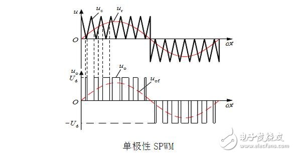
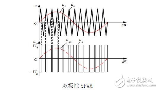
The principle of SPWM pulse generation is shown in the figure.
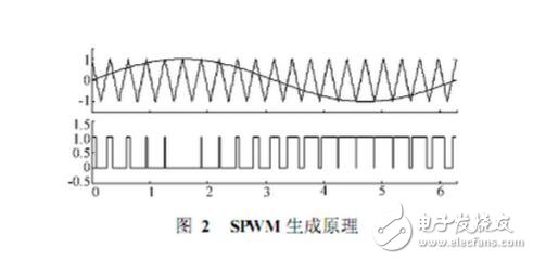
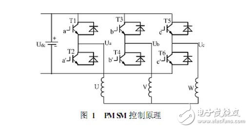
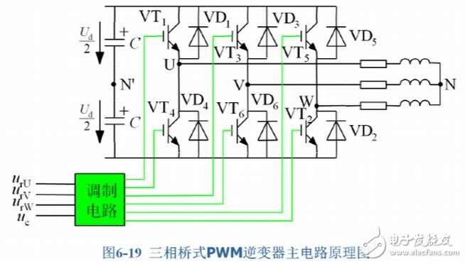
A sinusoidal signal is used as a reference modulated wave and compared with a high frequency isosceles triangular carrier to obtain a pulse sequence of equal pitch, equal amplitude but different width. The duty cycle of the pulse train is arranged in a sinusoidal manner. When the sine value is the maximum value, the pulse width is also the largest, and the interval between the pulses is the smallest; conversely, when the sine value is small, the pulse width is also small, and the interval between the pulses is large, which is the SPWM pulse. By controlling the turn-on or turn-off of the six IGBTs with six SPWM pulse trains, an AC signal can be obtained on the three-phase stator windings to drive the PMSM operation.
SVPWM algorithm
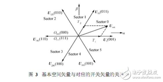
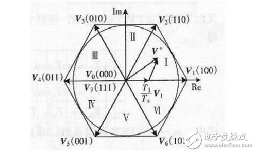
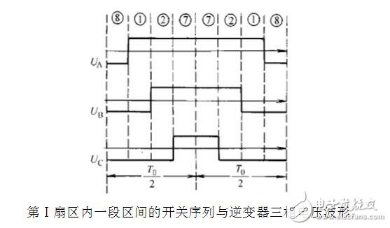
In Fig. 1, the switching vector [abc]T has a total of eight values, that is, a total of eight combinations of switching states of six IGBTs. These eight switching combinations determine eight basic space vectors, as shown in Fig. 3. The voltage Uout surrounded by two adjacent basic space vectors U0 and U60 is mapped onto the sum axis 6-8 to obtain Equation 1, where T represents a PWM cycle time length, and T1 and T2 are respectively in one cycle time T. The respective action times of the basic space vectors U0 and U60, T is the action time of the zero vector in one cycle, T0+T1+T2=T.
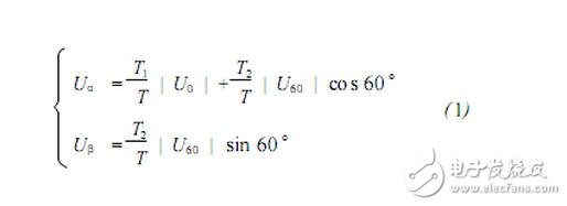
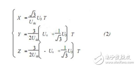
If Equation 2 is defined, the action times T1 and T29-10} of the two basic vectors surrounding this sector in one sector in one PWM period can be obtained, as shown in Table 1.
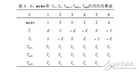
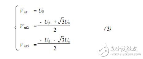
For Equation 3, define three variables a, b, c. If Vref1 "0", then a = 1, otherwise a = 0; if Vref2 "0", then b = 1, otherwise b = 0; if Vref3 "0", then c=1, otherwise c=0. Let N=4c+2b+a, it is easy to get the correspondence between N and the sector number sector, as shown in Table 1.
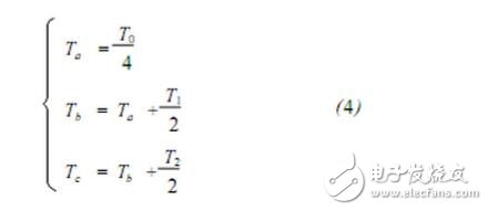
In order to ensure the duty ratio of the three-phase bridge arm in one PWM cycle, the comparison values ​​to be set are defined as Tcm1, Tcm2 and Tcm3, respectively, and Equation 4 is defined, then N and the number of sectors sector and Tcm 1, Tcm2 The relationship with Tcm3 is shown in Table 1. Comparing Tcm1, Tcm2 and Tcm3 with the DSP chip timer set to continuous increase/decrease mode, the PWM pulse is obtained, and the three bridge arms in Fig. 1 are controlled to be turned on and off, thereby generating phase in the 3-phase stator winding of PM SM. A sinusoidal waveform current with a difference of 120° forms a circular magnetic field that drives the motor to operate.
According to the principle that the waveform area is equal, the area of ​​each rectangular wave is equal to the sine wave area of ​​the corresponding position, and thus the rectangular wave of this sequence is equivalent to the desired sine wave. This modulation method is called sine wave pulse width modulation (SPWM), and this sequence of rectangular waves is called SPWM wave.
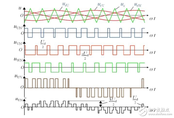
The picture shows a three-phase PWM waveform, in which
urU, urV, urW are U, V, W three-phase sinusoidal modulation wave uc is a bipolar triangular carrier;
uUN', uVN', uWN' are rectangular waveforms of phase voltage between the three-phase output of U, V, W and the neutral point N of the power supply;
uUV is a rectangular waveform of the output line voltage, and its pulse amplitude is +Ud and -Ud;
uUN is the phase voltage between the three-phase output and the midpoint N of the motor.
The classic SPWM control focuses on making the output voltage of the transformer inverter as close as possible to the sine wave, regardless of the waveform of the output current. The current hysteresis tracking control directly controls the output current to change around the sine wave, which is a step forward than requiring only a sinusoidal voltage. However, the ultimate goal of an AC motor requiring input of a three-phase sinusoidal current is to create a circular rotating magnetic field in the motor space, thereby producing a constant electromagnetic torque.
If this goal is aligned, the inverter and the AC motor are considered as one, and the operation of the inverter should be controlled in accordance with the tracking of the circular rotating magnetic field, and the effect should be better. This control method is called "magnetic flux tracking control", and the trajectory of the flux linkage is obtained by using different voltage space vectors, so it is also called "SVM (Space Vector PWM) control.
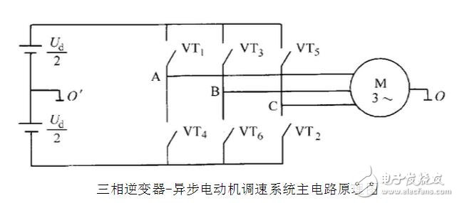
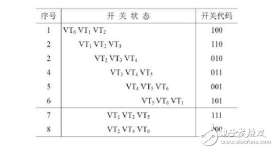
As the operating state of the inverter switches, the magnitude of the voltage space vector does not change, and the phase is rotated by π/3 each time until the end of one cycle. Thus, six voltage space vectors are rotated a total of 2π radians in one cycle to form a closed regular hexagon.
In one cycle, the six flux space vectors are radial, the tails of the vector are at point O, and the trajectory at the top is the regular hexagon surrounded by six voltage space vectors.
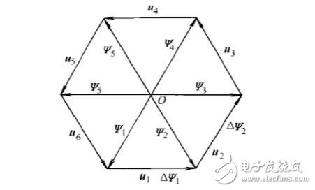
At any time, the direction of the resulting flux linkage increment is determined by the applied voltage, the magnitude of which is proportional to the time at which the voltage is applied. If the AC motor is only powered by a conventional six-step-step wave inverter, the flux trace is a hexagonal rotating magnetic field, which is obviously not the same as the circular rotating magnetic field generated when a sine wave is supplied. run. If you want to approximate the circle, you can increase the number of switching. It is assumed that the flux linkage is composed of 4 segments of 11, 12, 13, and 14 in the figure. At this time, the phase of the voltage space vector applied per segment is different, and can be obtained by a linear combination of basic voltage vectors.
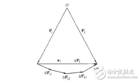
One working cycle of the inverter can be divided into six regions by six voltage space vectors, which are called sectors, as shown in I, II, III, and VI, and the time corresponding to each sector is It is π/3. Since the operating state of the inverter is symmetrical in each sector, the method of analyzing one sector can be extended to other sectors.
The modulation ratio is the ratio of the inverter output voltage to the DC bus voltage. The DC bus voltage utilization ratio refers to the ratio of the maximum amplitude Um of the AC voltage fundamental wave that can be output by the inverter circuit to the DC voltage Ud. In the SPWM, when the modulation degree is at most 1, the fundamental amplitude of the output phase voltage is Ud/2, the fundamental amplitude of the output line voltage is 3/2 Ud, and the DC voltage utilization is only 0.866.
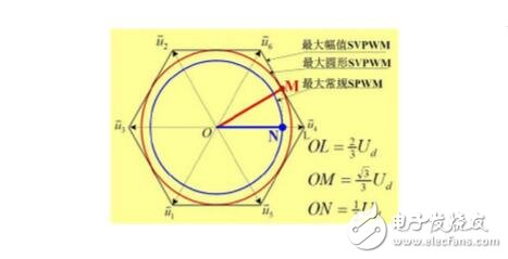
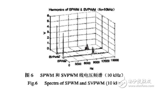
In SVPWM, the fundamental amplitude of the output phase voltage is equal to the fundamental amplitude of the output line voltage of 3/3 Ud, and the DC voltage utilization is 1. SVPWM has an 15.47% improvement in DC utilization over SPWM. The SPWM and SVPWM harmonics are mainly concentrated near the sampling frequency and its integer multiple, and the maximum value of the harmonic amplitude is rapidly attenuated as the sampling frequency multiple increases. From the perspective of harmonic distribution trend, SPWM is relatively concentrated and has a large amplitude: SVPWM is relatively dispersed and has a small amplitude. The total harmonic distortion rate calculated from Table 2 below shows that the harmonic content of the SVPWM output waveform is lower than the SPWM mode.
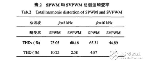
The traditional SPWM method is designed to generate a sinusoidal power supply with adjustable frequency regulation from the perspective of the power supply. The SVPWM method considers the inverter system and the asynchronous motor as a whole. The model is simple and convenient for real-time control of the microprocessor. The generation principle of SVPWM itself has nothing to do with PWM. Just like it, the driving waveform of SVPWM synthesis is very similar to PWM, so we call it PWM, and because this PWM is based on voltage space vector synthesis, so call it SVPWM is gone.
In summary, the principles and sources of SVPWM and SPWM are very different, but they do go the same way. The SPWM is modulated by a triangular wave and a sine wave, while the SVPWM can be seen as a modulation of a triangular wave and a sinusoidal fundamental wave having a certain third harmonic content. In contrast, SVPWM has the following main features:
(1) Although there are multiple switchovers between each cell, each switch involves only one device, so the switching loss is small.
(2) The three-phase PWM wave is directly generated by using the voltage space vector, and the calculation is simple.
(3) The maximum value of the fundamental voltage of the inverter output line is the DC side voltage, which is 15% higher than the output voltage of the general SPWM inverter.
Nanning Nuoxin Technology Co., LTD , https://www.nx-vapes.com