Today, I will introduce a national invention authorized patent-a new type of material pipe flowmeter. The patent was applied for by Shenzhen Shenlichang Electronics Co., Ltd., and the authorization was announced on May 31, 2017.
Content descriptionThe invention relates to a flow meter, in particular to a material conveying wind speed metering device in a material conveying system using wind power.
Background of the inventionAt present, there are several common types of material tube flow meters: First, the speed of the material in the material tube is measured by microwave and electrical measurement technology, thereby indirectly obtaining the wind speed in the pipeline. This method has the disadvantage of inaccurate measurement of the wind speed in the pipeline. ; Second, the straight pipe flowmeter is used to measure the wind speed. The flowmeter measures the pressure difference according to the frictional resistance loss of the airflow in the pipeline. The laboratory test shows that the pressure difference of the flowmeter is very small, and the pressure in the pipeline naturally fluctuates. It has a great influence on its pressure difference value, and there is also the disadvantage of poor measurement accuracy; third, Venturi flowmeter, which is commonly used in China at present, this type of flowmeter is designed and manufactured according to the principle of equal total pressure of each section, and through the section area The static pressure difference is obtained by the change of the static pressure difference. The size of the static pressure difference represents the size of the wind speed, and the change of the static pressure difference represents the change of the wind speed. The flowmeter obtains a large pressure difference and high measurement accuracy. However, the flowmeter still has certain problems. Because the material basically moves against the bottom of the pipe during the transportation process, when the material passes through the flowmeter, it will be blocked due to the resistance of the damping block, especially in the tobacco industry. In the process, the resistance will not only cause clogging of the tobacco, but also cause the tobacco to break. In summary, the existing flow meters, especially the Venturi flow meters used in the wind conveying material system, need to be improved.
Summary of the inventionThe technical problem to be solved by the present invention is to provide an improved flow meter, which is more conducive to the transportation of materials.

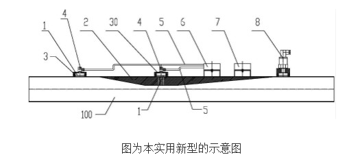
The technical solution adopted by the present invention to solve its technical problem is: a new type of material tube flow meter, including a tube body, the top of the inner wall of the middle part of the tube body is provided with a pipeline damping block, and the middle to the front and back ends of the pipeline damping block Gradually narrowing, and the middle thickness of the pipeline damping block is larger than the front and rear ends; the first gland, the second gland and the pressure difference transmitter are installed outside the tube body, and the first gland and the second gland are all connected with each other. The pipe body is internally connected, wherein the first gland is installed at the front end of the pipe body, the second gland and the middle position of the pipeline damping block correspond to each other, and the first gland is connected to the differential pressure transmitter through a hose The positive interface, the second gland is connected to the negative interface of the differential pressure transmitter through a hose; a junction box for communicating the differential pressure transmitter and the controller is also installed on the pipe body.
As in the new material tube flow meter described above, a gas filter device is arranged between the first gland, the second gland and the tube body. Both the first gland and the second gland are connected and fixed with corresponding hoses through hose joints. A pressure sensor connected to the controller through a junction box is installed at the rear end of the pipe body.
The implementation of the technical solution of the present invention has at least the following beneficial effects: the reasonable setting of the damping block structure can reduce the probability of blockage during the material conveying process, and can also reduce the fragmentation of materials such as tobacco, and improve the wire feeding. quality.
Ningbo Autrends International Trade Co.,Ltd. , https://www.supermosvape.com