In the process of porting to different architectures, if developers only focus on MIPS, only using MIPS to predict the computing performance required by the application will be very wrong. This article will analyze the various architectural features of the MCU/SoC for typical computational problems. The purpose is to show that MIPS does not truly reflect the computational performance of the device and explore how we should respond to this problem. In addition, given the relatively few benchmarks that compare the system-level functionality of such products, this article will focus specifically on MCU/SoC devices operating at speeds below 100MHz.
Features below 100MHz architecture
Below 100MHz MCU usually uses 8-bit, 16-bit or 32-bit architecture, the data bus width is 8-bit, 16-bit or 32-bit. These products can also be divided into other types, such as Harvard/Von Neumen, RISC, and CISC, each of which has its own interesting differences. For most MCUs, different instructions need to perform different machine resources. In addition, the oscillator frequency is usually different from the machine's duty cycle. For example, with the classic 8051, the oscillator's 12 cycles are equivalent to 1 cycle of the machine's operation. For many PIC devices, 4 oscillator cycles correspond to 1 machine duty cycle.
Below we use an example to better illustrate this issue. Assume that the oscillator frequency of a device is 20MHz, and its two oscillator cycles correspond to 1 machine duty cycle. In addition, instruction execution requires 1 to 6 machine duty cycles. So, what is the MIPS rating for this device? We divide the oscillator frequency by two to get a usable machine cycle of 10 million. However, how to convert machine work cycles to MIPS depends on how we look at this issue. If you are a marketer, you will only focus on the best case, that is, assuming that each instruction takes only one working cycle, so that the performance of this product is 10 MIPS. If you want to understand the lowest theoretical performance, then it will be assumed that each instruction takes 6 cycles, which results in 1.66 (10/6) MIPS. Here we have the highest and lowest MIPS. For a typical application, the actual MIPS performance is somewhere in between, depending on the instruction set combination of the application. We also made an assumption here that different architectural instructions have similar computing performance, but this is basically unrealistic.
We assume here that the number of machine cycles is the only factor that determines the number of instructions executed by the device. Below, we imagine the impact of flash on processing performance. In general, flash provides data at a rate of no more than 20 MHz. Therefore, if the CPU runs faster than 20MHz and executes instructions with flash, the flash data rate becomes the biggest bottleneck. In this case, we can solve the above problem by making the flash bus bandwidth higher than the data bus bandwidth and creating an instruction buffer to keep up with the instruction rate. To do this, the CPU will call the next instruction when executing the current instruction. This is no problem with linear code. Unfortunately, the actual system code is rarely linear. Each time the code branches, the instruction buffer must be reconstructed. Another way to improve performance is to add cache capacity. In short, if one MCU/SoC manages flash with high efficiency and the other is less efficient, the performance data will be very different even if the machine has the same duty cycle and instruction set.
We are already familiar with various factors such as the above, and developers often consider these related factors when comparing the performance of different devices. Let's talk about some less obvious factors.
Effect of DMA on MIPS
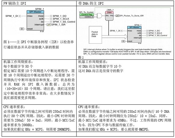
An MCU/SoC device supports the DMA (Direct Memory Access) function, which frees the CPU from memory access to improve performance. How do we evaluate the impact of DMA on MIPS? Let's first take a look at the typical use of the serial communication protocol SPI in main mode. SPI is a good example because it is usually the highest throughput onboard communication peripherals on MCU/SoC and it is used with memory, Ethernet, wireless transceiver chips, etc.
assumed:
SPI rate: 8Mbps
Packet size: 128 bytes Data throughput requirements: 160uS per packet
If the SPI rate is 8 Mbps, 1 uS is required to transmit 1 byte. Therefore, 128uS is required to transmit 128 bytes. Our budget is 160uS per packet, leaving 32uS (160-128) for SPI management. This 32uS budget is evenly allocated to 128 bytes because each uS of the system will load a new data byte. Divide 32uS by 128 to get SPI management There is 250nS time per data byte transfer.

For the above example, the DMA reduced the MCU/SoC rate requirement by 160 MHz and reduced the CPU processing power requirement by 200 MHz. If we assume that one cycle is equivalent to MIPS, the DMA of this application is equivalent to a 200 MIPS processor.
The efficient MIPS implemented by the DMA depends to a large extent on throughput requirements. Let us give an extreme example of this application. Assuming there is no time limit for each data packet, then the DMA saves 50 CPU cycles per byte, so for the 128 bytes, the cycle number can save up to 6400. If the MCU needs to support 8MHz SPI at 16MHz, and 128 bytes of data packets are transmitted only once per second, the DMA/SoCs that do not support the MCU/SoC operation rate need to reach 16,006,400 instructions per second, the performance level and support DMA. The MCU has 1.6 million instructions per second. Therefore, for this particular use case, the impact of DMA is negligible.
Coprocessor impact on MIPS
It is not uncommon for an MCU/SoC to have a coprocessor. The coprocessor can handle some high computational intensity tasks in parallel, liberating the CPU and increasing the processor's MIPS efficiency.
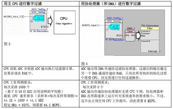
Let us imagine an application where the input audio data is sampled by the ADC and the sampling frequency is 44.1Ksps. Suppose we want to suppress the linear frequency of 50 or 60 Hz. To do this, we need to use a digital band-stop filter.
Sample rate: 44.1Ksps, sampling interval 22.7uS
FIR filter taps: 128
To simplify the explanation, we do not consider the output stage of the filter.

For the above example, the coprocessor reduced the CPU rate requirement by 44.1 MIPS. Please note that this example uses a simple FIR filter. If more sophisticated filters are required, MIPS requirements may be much higher (hundreds of MIPS).
The Impact of Programmable Digital Devices on MIPS
The programmable digital logic of some MCU/SoC devices is in the form of a CPLD or FPGA logic, which allows developers to implement CPU functions in hardware, which is traditionally implemented in software. Let's take a look at the impact of programmable digital logic on MIPS.
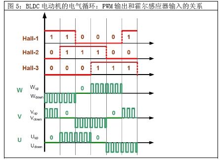
Let's assume a three-phase brushless DC (BLDC) motor with a speed of 30,000 rpm. The rotation of the motor requires pulse timing. For the sake of simplicity, we also assume that hall sensors are used to detect the position of the rotor of the motor. Three such Hall sensors are used to achieve the above purpose. At 60 degrees per revolution, one of the hall sensor outputs changes. If the motor has two sets of rotor poles, then two electrical cycles will correspond to one mechanical rotation. This means that Hall sensor output will change 12 times for a complete rotation. Hall sensor output causes 6 PWM output changes. Each of the three PWMs with associated outputs is used to create six PWM outputs. The following figure shows the relationship between Hall sensor inputs and PWM outputs. A positive PWM value indicates a high voltage side PWM operation, and a negative value indicates a PWM low side operation.

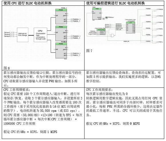
Let's analyze how BLDC conversion is usually implemented and how the BLDC conversion can be simplified if the device has programmable logic (CPLD or FPGA) functionality.

For the above example, programmable digital technology reduced the CPU rate requirement by 1 MIPS. If the motor speed is low, then the technology has a lower impact on MIPS, and vice versa. The above example uses optimized assembly and simple open-loop control. Practical applications can be more complex and often use C code to simplify maintenance and reuse. If you use generic C code, MIPS requirements increase to 3 MIPS. Almost all motor control applications require multiple control loops similar to PID control, which increases the computational requirements. However, if you do the same work through hardware, you can ensure that CPU usage is zero. Therefore, the MIPS requirement for the entire motor control application is between 5 and 10 MIPS. With the hardware approach, the demand is zero.
The implementation based on programmable logic has high reusability and there are no integration problems. The programmable digital logic required to implement a motor control is very low, so we can implement multiple motor control and conversion logic in hardware. If we do the same job with the CPU, because we can't handle two interrupts at the same time, the MIPS demand will grow several times. In addition, in order to guarantee a reasonable interrupt response time, the CPU must run at a much faster rate than the minimum rate requirement. Therefore, we can easily implement a complete BLDC motor control system with programmable logic, such as four such systems. However, if you use the MCU firmware to achieve the same task, you need approximately 100 MIPS of performance.
As described in this article, MIPS does not represent the true ability of MCU/SoC devices to solve system-level problems. If the device has all the above capabilities, what kind of device MIPS performance is applicable? 200 MIPS, 500 MIPS, or 1,000 MIPS? In all cases, MIPS is only a very limited number.
So how do developers determine the best device for the application? Unfortunately, this problem is not easily answered:
Identify areas in your application where critical timing or CPU performance requirements exist.Determine if the MCU/SoC vendor provides application notes or sample projects that are similar to your desired application. If provided, it will provide guidance on how well you can optimize your application for a given MCU/SoC. If not, you should find a way to find potential ways to implement your application using a given architecture and understand what hardware features you can use.
The MIPS performance requirements are roughly estimated based on the above example. The calculation does not have to be particularly precise. You should try to determine the potential huge gap. In all of the above examples, the performance difference is large enough that accurate calculations are not necessary.
If the performance gap is small, such as between 10% and 20%, and the task is the main component of the application, the only option is to use the vendor's development kit to create a specific implementation and detect the actual performance gap.
If you plan to purchase a large number of devices, the requirements can be part of an RFQ (Request for Quotation). This allows vendors to provide device performance-related information based on your specific application.
Electronic components are components of electronic components and small machines and instruments. They are often composed of several parts and can be used in similar products; often refer to certain parts of electrical appliances, radios, instruments and other industries, including capacitors, transistors, General term for electronic devices such as hairspring and spring
Components Sourcing,ADS8168IRHBT,10M50DAF484C8G,Chip,Components Supplier
Huizhou Liandajin Electronic Co., Ltd , https://www.ldjcircuitboard.com