Display principle of dot matrix LCD
In the digital circuit, all data is saved in 0 and 1, and different data operations are performed on the LCD controller to obtain different results. For the display of English operations, since there are few English letters, only 8 bits (one byte) are needed. For Chinese, there are more than 6000 commonly used, so our DOS predecessors thought of a way to express the Chinese characters, that is, the internal code of Chinese characters, by using the two values ​​of the ASCII table that are rarely used. The remaining low 128 bits are reserved for English characters, which is the English internal code.
Then, after getting the inner code of the Chinese character, it is only a set of numbers, then how to display it on the screen? This involves the font of the text. Although the font is also a set of numbers, its meaning has a fundamental change with the meaning of the number. It uses the information of each digit to record the shape of English or Chinese characters, such as the English 'A 'The way in which the font is recorded is shown in Figure 1:
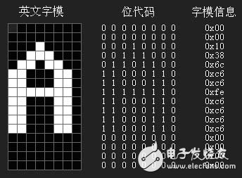
Figure 1 "A" font map
The Chinese "you" in the font is recorded as shown in Figure 2:
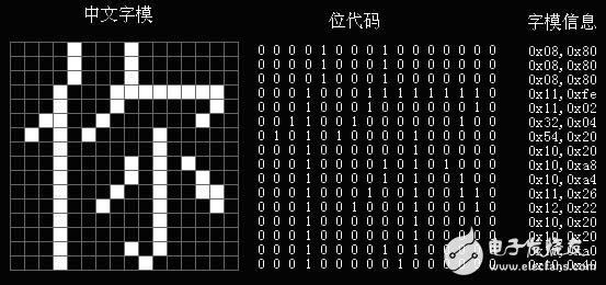
Figure 2 "You" font map
12864 dot matrix LCD introduction
12864 is a graphic dot matrix liquid crystal display, which is mainly composed of a row driver/column driver and a 128&TImes; 64 full dot matrix liquid crystal display. The graphic display can be completed, and 8 & TImes; 4 (16 & TImes; 16 dot matrix) Chinese characters can be displayed.
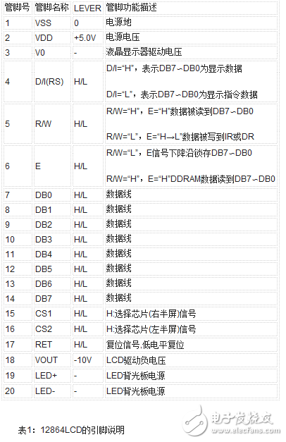
Before using the 12864LCD, you must understand the following functional devices to be able to program. The 12864 internal functional devices and related functions are as follows:
Instruction register (IR)
IR is used to register the instruction code and corresponds to the data register data. When D/I=0, the instruction code is written to IR under the action of the falling edge of the E signal.
2. Data register (DR)
The DR is used to register data and corresponds to an instruction register register instruction. When D/I=1, the graphic display data is written to DR under the action of the falling edge, or is read by the DR to the DB7∽DB0 data bus under the action of the E signal high level. The data transfer between the DR and the DDRAM is performed automatically within the module.
3. Busy sign: BF
The BF logo provides internal working conditions. BF=1 means that the module is operating internally, at which point the module does not accept external commands and data. When BF=0, the module is ready to accept external commands and data at any time.
With the STATUS READ command, BF can be read to the DB7 bus to verify the operating status of the module.
4. Display control trigger DFF
This trigger is used to control the on and off of the module screen display. DFF=1 is DISPLAY OFF, the content of DDRAM is displayed on the screen, and DFF=0 is OFF (DISPLAY OFF).
The state of the DDF is controlled by the DISPLAY ON/OFF and RST signals.
5. XY address counter
The XY address counter is a 9-bit counter. The upper 3 bits are the X address counter, the lower 6 bits are the Y address counter, the XY address counter is actually the address pointer of the DDRAM, the X address counter is the page pointer of the DDRAM, and the Y address counter is the Y address pointer of the DDRAM.
The X address counter has no counting function and can only be set with instructions.
The Y address counter has a loop count function. After each display data is written, the Y address is automatically incremented by one, and the Y address pointer is from 0 to 63.
6. Display data RAM (DDRAM)
DDRAM stores graphics display data. A data of 1 indicates display selection, and a data of 0 indicates display non-selection. The relationship between DDRAM and address and display location can be found in the DDRAM address table.
7. Z address counter
The Z address counter is a 6-bit counter that has a loop count function that is used to display line scan sync. When a line scan is completed, the address counter is automatically incremented by one, pointing to the next line of scan data, and the Z address counter is 0 after RST reset.
The Z address counter can be preset with the command DISPLAY START LINE. Therefore, the start line of the display screen is controlled by this instruction, that is, from which line the data of the DDRAM is displayed on the first line of the screen. This module has a total of 64 lines of DDRAM, and the screen can scroll through 64 lines.
12864LCD instruction system and timing
The instruction system of this type of liquid crystal display module (ie KS0108B and its compatible control driver) is relatively simple, and there are only seven kinds in total. Its instruction list is shown in Table 2:
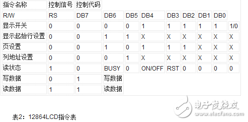
Each function instruction is described below.
Display on/off command
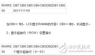
The instruction sets the line number of the display RAM corresponding to the uppermost line of the liquid crystal screen, and regularly changes the display start line, so that the LCD can realize the effect of displaying the scrolling.
3, page (PAGE) setting instructions
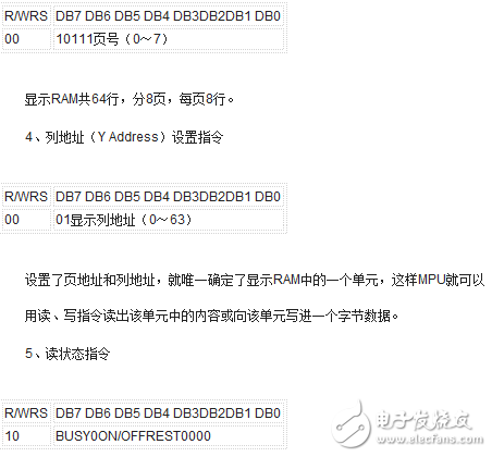
This command is used to query the status of the internal controller of the LCD module. The meanings of the parameters are as follows:
BUSY: 1- Internal at work 0 - normal state
ON/OFF: 1-display off 0-display on
RESET: 1-reset state 0 - normal state
In the BUSY and RESET states, all commands except the read status command do not affect the liquid crystal display module.
The BUSY state is queried before the operation of the liquid crystal display module to determine whether the liquid crystal display module can be operated.
6, write data instructions
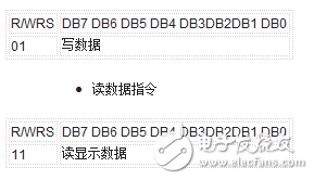
11 read display data
The column address is automatically incremented by one for each read and write operation of the read and write data instructions. It must be noted that there must be a blank read operation before the read operation, and then read again to read the data in the unit to be read.
12864 dot matrix LCD hardware and software design example
Through the above study, the software and hardware design of the 12864LCD is now applied. This example will display the content shown in Figure 3 on the LCD:
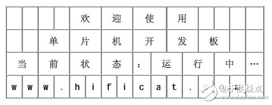
Figure 3 simulation display renderings
Switch the display switch to the LCD display state before debugging.
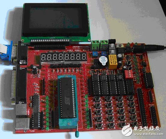

Figure 4 128*64LCD experiment diagram
Hardware schematic
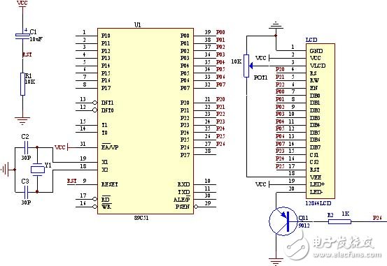
Figure 5 hardware schematic
Program flow chart

Figure 6 software flow chart
Software code
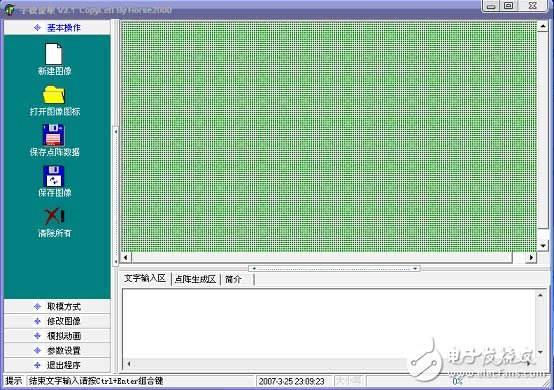
Before writing software code, you must first master the method of kanji modulo. To get the text in the above table, we can use the modulo software to complete. At present, there are many modulo software for dot matrix LCD. We take the modulo software supported by this development board as an example to introduce the modulo method of Chinese characters.
Open the modulo software and the following display interface appears:
Enter the text in the text input area. Let's take a welcome “Happy†word as an example to understand its modulo process. After entering "Happy" in the text input area and pressing CTRL+ENTER, you will see that the word "Hua" has been displayed in the analog display area.
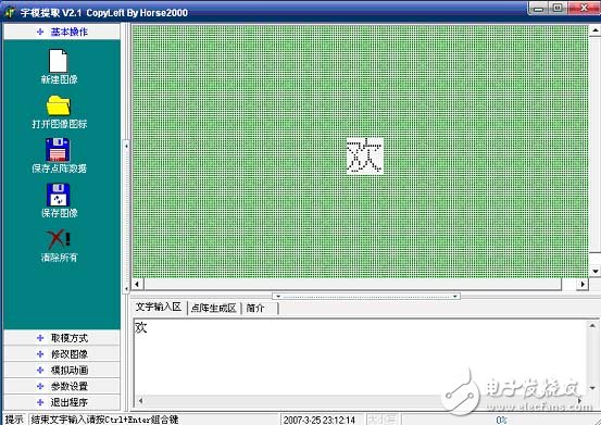
In the "modulo mode", select "C51 format" to get the display code of the Chinese character "Happy" in the "Dot Matrix Generation Area".


After the above steps, a Chinese character is successfully taken. In the program, just call this code to display the Chinese character "Happy", and other Chinese characters use the same method. After we have finished all the Chinese character codes to be displayed, we can program them.
Small computer system interface (SCSI) is an independent processor standard for system level interfaces between computers and intelligent devices (hard disks, floppy drives, optical drives, printers, scanners, etc.). SCSI is an intelligent universal interface standard.
Small computer system interface (SCSI) is an independent processor standard used for system level interface between computer and intelligent devices (hard disk, floppy drive, optical drive, printer, scanner, etc.). SCSI is an intelligent universal interface standard
SDR+V.26 SCSI Section
ShenZhen Antenk Electronics Co,Ltd , https://www.atkconnectors.com