Introduction For the clock requirements of most microcontrollers, silicon oscillators are a simple and effective solution. Unlike crystal and ceramic resonators, silicon timer devices are insensitive to vibration, shock, and electromagnetic interference (EMI. In addition, silicon oscillators do not require careful matching of timing components or strict circuit board wiring.
In practical applications, in addition to some environmental factors, the selection criteria of the clock source usually depends on four basic conditions: accuracy, supply voltage, size, and noise. The accuracy requirements usually depend on the communication standard used for a particular application. For example, high-speed USB requires an overall clock accuracy of ± 0.25%. In contrast, a system that does not require external communication may only need 5%, 10%, or even 20% clock source accuracy to work well. Comparison of Silicon Oscillator and Crystal or Ceramic Resonator The typical supply voltage of a microcontroller clock is 1V to 5.5V, while the typical supply voltage of a silicon oscillator is 2.4V to 5.5V.
Clock noise is affected by many factors, including amplifier noise, power supply noise, circuit board wiring, and the inherent noise suppression characteristics of the oscillating element (or quality factor "Q"). The Q value of the crystal is very high, and the noise generated is generally the smallest. It is especially suitable for systems requiring low baseband noise, such as audio CODEC.
However, silicon oscillators take up minimal space and do not require additional timing elements. For most silicon oscillators, the external components required are usually only a power supply bypass capacitor. Pierce oscillator crystals and ceramic resonators are mostly used in Pierce oscillators, where the crystal or resonator is used as the tuning element in the feedback of the inverting amplifier. In order to make the circuit stable, it is necessary to add capacitors and resistors for phase shift compensation and gain control. In addition, a certain damping must be provided with a resistor to prevent permanent damage to the crystal or resonator caused by overdriving.
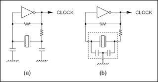
Figure 1 shows two examples of Pierce oscillators. Figure 1a is a typical crystal oscillation circuit, using external capacitors and resistors. Figure 1b is a Pierce oscillator based on a three-terminal ceramic resonator with integrated compensation capacitors. The value of each element in these designs depends on the operating frequency, supply voltage, inverter type, element type (crystal or resonator), and manufacturer.

Figure 1. Pierce oscillator using crystal and three-terminal ceramic resonator
The most common way to implement Pierce oscillators is to use a CMOS NOT gate as the amplifier. Although the stability and power consumption performance of this scheme is generally inferior to transistor-based oscillators, CMOS inverter-based circuits are relatively simple and are very practical in many cases. Both buffered and unbuffered inverters can be used for amplifying components, of which unbuffered inverters are preferred because they work more stable, although they are accompanied by increased power consumption. Unbuffered gates do not have a powerful output stage, so a standard inverter must be used to buffer the long traces on the circuit board. Advantages of silicon oscillator Silicon oscillator, this fully integrated oscillator is the simplest clock source. These devices can generate a square wave of a specified frequency, which can be directly fed into the clock input of a microcontroller (µC). Silicon oscillators do not rely on mechanical resonance characteristics to obtain the oscillation frequency, but are based on an internal RC time constant. This design makes the silicon device insensitive to external mechanical effects. Moreover, unlike traditional oscillators, there are no exposed high-impedance nodes, which allows silicon oscillators to withstand greater humidity and EMI effects. Application of silicon oscillator If you use silicon oscillator instead of crystal or ceramic resonator, you can first remove all components related to the oscillation circuit. This usually includes one to two resistors and two capacitors (if they are not included in the resonator package). The oscillator can be installed in an appropriate location, and then its clock output is led to the microcontroller (µC) clock input (OSC1) pin. The power supply for the oscillator should come from the power supply driving the µC clock input circuit.
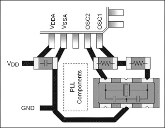
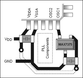
Figures 2 and 3 show an example of this design, which shows the oscillation circuit for the MC68HC908 µC. Figure 2 shows the recommended circuit, a three-terminal ceramic resonator. Figure 3 shows a circuit using a silicon oscillator. In this example, the MAX7375 and SC70 packages are used. The external dimensions including pins are only 2.0mm x 2.1mm.

Figure 2. MC68HC908 µC uses an oscillator based on a three-terminal resonator

Figure 3. The MC68HC908 µC uses the MAX7375 silicon oscillator
The layout of the silicon oscillator on the circuit board usually does not have high requirements, because this device outputs a low-impedance square wave, it can transmit a sufficient distance on the circuit board, and there is no need to worry about the interference of other signals on it. Silicon oscillators can drive multiple devices. Like any other high-speed signal, the clock output of a silicon oscillator generates electromagnetic radiation when driving long wires. Pins close to the clock generator can be connected with a resistor in series with each clock signal to reduce this radiation. As shown in Figure 4, when the MAX7375 drives two clock circuits, a resistor is connected in series on each clock line.

Figure 4. Series resistance reduces electromagnetic radiation
High Voltage STA Armored Cable
High Voltage STA Armored Cable is a type of Power Cable that is designed to carry high voltage electricity in a safe and efficient manner. It is commonly used in industrial and commercial applications where high voltage power is required for heavy machinery and equipment.
The cable is constructed with a solid or stranded copper conductor, which is insulated with a high-quality material such as XLPE or EPR. The insulation provides excellent electrical properties, such as high dielectric strength and low capacitance, which ensures that the cable can handle high voltage without any breakdown.
The cable is then wrapped with a layer of galvanized steel tape armor, which provides mechanical protection against external damage, such as impact and abrasion. The armor also helps to prevent the cable from being damaged by rodents and other animals.
Finally, the cable is covered with a sheath made of PVC or PE material, which provides additional protection against moisture, chemicals, and other environmental factors. The sheath also makes the cable more resistant to fire, which is important in industrial and commercial settings.
Overall, High Voltage STA Armored Cable is a reliable and durable solution for carrying high voltage power over long distances. It is available in a range of sizes and specifications to meet the specific needs of different applications.
PVC Sheathed Electric Cable,Copper Conductor Power Cable,High Voltage Xlpe Power Cable,High Voltage XLPE Insulated STA Armoured Power Cable,STA Armour High Voltage XLPE Cable
Ruitian Cable CO.,LTD. , https://www.rtpowercable.com