Urban road lighting is increasingly using LED lighting technology instead of traditional lighting technology, the purpose is to reduce the consumption of electrical energy. Since the LED uses a low-voltage DC power supply, it is convenient to add additional detection and control circuits, which facilitates the intelligent management of the street lamp network and further saves energy and reduces consumption. For the management and control of streetlight networks, both power carrier communication technology and rapid development of technology can be adopted, making short-range wireless communication technology superior to power carrier communication technology in terms of application cost, reliability and communication rate, for example. Zigbee short-range wireless communication technology. This paper proposes a solution to build a LED street light wireless sensor network using short-range wireless communication technology. It can control the switching, dimming, etc. of any single or multiple lamps in the LED street light network. , current parameters and other tests to achieve intelligent management of the LED street light network. As a wireless sensor network, its architecture should include four basic levels: the physical layer and the data link layer, the network layer, and the application layer. The LED street light wireless sensor network adopts the IEEE 802.15.4 standard as the technical standard of its physical layer and data link layer. The network layer is integrated with the application layer, and three relay communication modes: single-hop, double-hop and jump-hop are adopted as the network. The basis of the agreement. This paper focuses on the architecture of LED wireless sensor network, based on the network topology and the composition of communication nodes, discusses the protocol packet format of the network layer, the working principle of routing, and the design flow of node communication.
Network system
The network system of the wireless sensor network is the basis for the network layer to implement routing, including node composition and network topology.
Composition of street light sensor network nodes
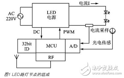
The street light network consists of a number of street lamps with even spacing. Each LED street light is a communication node of the network used to construct a wireless sensor network. As shown in FIG. 1 , in order to construct a wireless sensor network LED street light node, in addition to the circuit of the illumination part, circuits for sampling the LED current, detecting the brightness of the LED light, and PWM controlling the brightness of the LED light are added. Each LED street light is both a sensor node and a network routing node; each node contains a microcontroller (MCU, such as cc2530), which has RF communication function, which can both transmit signals and receive signals; each node has 32 bits (bits) The unique ID number of ). By adopting the IEEE 802.15.4 protocol standard at the physical layer and the MAC layer, and combining the protocols of the network layer and the application layer, all of these nodes are organically combined to form an LED street light wireless sensor network. Since some existing network layer and application layer protocols such as Zigbee and RF4CE are not very suitable for LED street light sensor network applications, network layer and application layer protocols need to be redesigned.
Network topology
According to the distribution rule of LED street lamps, each LED street lamp forms a wireless communication network as a network node. Its topology is shown in Figure 2. (a) is a signal point-by-point (single-hop) relay transmission topology diagram, and (b) is a signal. The separation point (double hop) relay transmits the topology map. To facilitate the design and discussion of the following network application protocols, the following definitions are made:
(1) All nodes can be divided into two categories, namely LED street light nodes (referred to as LED nodes, such as a1 a2 ... an , b1 b2 ... bn) and street lamp controller nodes (referred to as control nodes, such as a, b);
(2) The distance between adjacent nodes is L, and the wireless signal coverage radius of each node is greater than or equal to 2L;
(3) According to the relative position of the nodes, the nodes can be divided into the predecessor node and the successor node, the predecessor node is close to the controller, and the successor node is far from the controller. For example, a1 is the a2 precursor node, a3 is the a2 successor node; the same b2 is the b4 precursor node, b6 is the b4 successor node, and so on.

(4) Between the control node and the LED node, the LED nodes can communicate with each other as long as the wireless signal can be covered, and there is no need to set up a base station or a special route coordination device.
(5) The 32-bit unique ID number of each node consists of two parts, namely the network ID and the node address (number), both of which are 16 bits. The network IDs of all nodes in the same streetlight network are the same; starting from the control node, the node addresses are arranged in order from small to large.
Network protocol
The street light sensor network protocol includes the definition of protocol package and the definition of routing protocol. Its design goal is simple, practical and easy to implement.
Network protocol packet format
There are three types of information packets transmitted by the street light sensor network protocol, which are command packets, parameter packets, and response confirmation packets.
(1) Command package
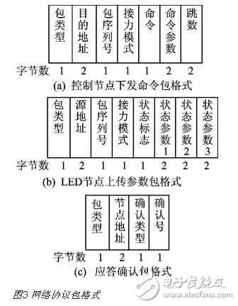
Figure 3 (a) shows the format of the command packet delivered by the controller node to the LED street light node. There are three types of commands: broadcast commands for all LED nodes throughout the network, group commands for partial LED nodes, and single point commands for individual LED nodes.
The fields of the command packet are defined as follows:
Package type: 1;
Destination address: the address of the specified LED node;
Packet serial number: the number of the packet sent to the specified node;
Relay mode: when it is 1, it means single-hop mode; when it is 2, it means double-hop mode even chain; when it is 3, it means double-hop mode odd chain;
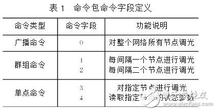
The definition method of the command field is shown in Table 1. Table 1 only lists some commands. In practice, you can add commands as needed.
Table 1 Command Packet Command Field Definitions
Command parameter field: used to indicate the brightness of dimming. The smaller the value, the lower the brightness of the LED, and the less power consumption. When the value is 0, it means to turn off the light;
Hop count: The number of nodes that the command needs to pass to the destination address. The maximum value is the number of all LED nodes in the street light network. When a command packet is transmitted, the hop count is decremented by 1 each time it is forwarded. When the hop value is 0, the command packet is no longer forwarded.
(2) Parameter package
Figure 3 (b) shows the format of the parameter packet uploaded by the LED street light network node. The control node can obtain the state parameters of each LED node in the network by using timed polling or instant query mode, such as current value, brightness value, etc., and each LED node will send parameters to the control node only after receiving the command to read the parameter. package. The parameters of each parameter field are defined as follows:
Package type: 2;
Source address: the address of the LED node for uploading parameters;
Packet serial number: the parameter packet number sent for the upload parameter LED node;
Relay mode: Since the parameter packet is sent only after the node receives the read status parameter command, the relay mode of the parameter packet is determined by the relay mode of the command packet;
Status flag: 0, indicating that the corresponding LED node has no fault; 1 means that the corresponding node has a fault; 2 means that the corresponding node and the successor node are faulty;
State parameter 1-3: is the relevant parameters of the LED node, such as current value, voltage value and LED brightness value.
(3) Response confirmation package
As shown in Figure 3(c), the packet format is acknowledged. In order to achieve reliable transmission, each node needs to send a response confirmation packet after receiving the command packet or parameter packet. If the sending (forwarding) party of the packet does not receive the response confirmation packet within the set time, the retransmission of the packet is initiated. The values ​​of the fields of the response confirmation packet are defined as follows:
Package type: 3;
Node Address: The address from which the Acknowledgement Packet node is sent.
Confirmation type: The type of package that received the packet;
Confirmation number: the serial number of the packet that the node received the packet;
Network routing protocol
The core of the street light sensor network routing protocol is the forwarding mechanism of each node to the information packet. Since each node's signal coverage is limited, its information can only be sent to neighboring nodes. If you want to send information to a distant node, you can only rely on multiple forwarding of intermediate nodes. According to the conditions defined in the foregoing 1.2, the node forwarding information packet can be divided into three modes, namely, a single-hop relay mode, a double-hop relay mode, and a variable-jump relay mode, and each LED node will select according to the definition of the relay mode field in the packet.
Single jump relay mode
Figure 2 (a) shows the topology of the single-hop relay mode. It is a relatively simple forwarding mode, which requires that each node's wireless signal coverage radius is larger than the node spacing L, and the information packet only needs to be forwarded to the adjacent predecessor node or successor node. In this mode, the method by which the node processes the received packet is as follows:
After the 1 node receives a command packet (as shown in Figure 3(a)), the forwarding node sends a Receive Acknowledgement Reply packet; the hop count in the command packet is decremented by 1; the node's own address (NA) is compared with the size of the destination address in the command packet. If it is equal, the command in the package is executed and the command packet is not required to be forwarded. If it is not equal, the packet is forwarded to the successor node; if it is a broadcast command (the target address value is 0xffff), the command is executed at the local node and the subsequent node is also forwarded to the subsequent node. Command package. The routing address when forwarding is: NA+1. When the command packet is delivered to the last LED node in the network, the hop count will be 0 after decrementing by 1, and the packet will no longer be forwarded.
After receiving the parameter packet (as shown in Figure 3(b)), the 2 nodes only need to send the receiving acknowledgement packet and the forward node forwarding to the successor node, and the routing address of the forwarding parameter packet is: NA-1.
After receiving the command packet or parameter packet, the 3 node must send a receiving acknowledgement packet (as shown in Figure 3(c)). When the command packet is received, the acknowledgement type value is 1, and the routing address of the response acknowledgement packet is NA-1. When the parameter packet is received, the confirmation type value is 2, and the routing address of the response acknowledgement packet is NA+1.
Double jump relay mode
Figure 2 (b) shows the topology of the double-hop relay mode. This mode requires that each node's wireless signal coverage radius range ≥ 2L. As can be seen from FIG. 2, the double-hop relay mode spans two nodes at a time, and the number of times of transmitting a packet to a designated node is less than half of that of a single-hop relay mode, so the transmission delay is also small. In the double-jump relay mode, all LED nodes of the entire network are divided into two relay chains according to the parity of their address values, namely, an odd address node chain and an even address node chain. When the control node sends a broadcast command, it needs to be separately sent for the odd address node chain and the even address node chain, and the command information packets are simultaneously propagated on the odd address node chain and the even address node chain respectively. In the double-hop relay mode, the node processes the received packet as follows:
The processing method after the 1 node receives the command packet is basically the same as the single-hop relay mode, but the routing address when the packet is forwarded becomes: NA+2.
2 The processing method after the same node receives the data packet is also basically the same as the single-hop relay mode, except that the routing address at the time of packet forwarding becomes: NA-2.
After receiving the command packet or parameter packet, the 3 node must send the receiving acknowledgement packet. When the command packet is received, the acknowledgement type value is 1, the routing address of the response acknowledgement packet is NA-2, and the confirmation type is received when the parameter packet is received. The value is 2, and the routing address of the acknowledgement packet is NA+2.
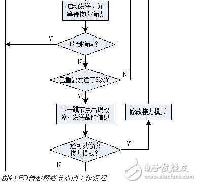
Regardless of whether it is a single-hop relay mode or a double-hop relay mode, after the node sends a command packet or a parameter information packet and does not receive the confirmation packet within the specified time, it needs to resend, and the number of retransmissions is generally not more than three.
Jump relay mode
The jump jump relay mode is actually a supplement to the single jump relay mode and the double jump relay mode, and is mainly used when a communication fault occurs in the next hop node. When working in the single-hop relay mode or the dual-hop relay mode, if the response confirmation packet of the next hop node is not received after multiple retransmissions, it indicates that the next hop node has a communication failure. At this time, by changing the relay mode, the single-hop double-hop or the double-hop single-hop can bypass the next-hop node with communication failure and continue the relay transmission of the packet. At the same time, the relevant information of the faulty node is fed back to the control node. The variable jump relay mode requires that each node's wireless signal coverage radius range ≥ 2L. The jump relay mode is divided into two cases:
(1) Initial transmission is single-trip relay mode
Let the address of the LED node i be NAi. When the LED node i forwards the command packet (or parameter packet) in the single-hop mode, even if the retransmission is performed, the confirmation packet of the LED node i+1 (or i-1) is not received. Then it is concluded that the next hop node has failed. At this time, if the command packet is transmitted, it is executed from 1; if the parameter packet is transmitted, 2 is executed, because the faulty node has already encountered when transmitting the command packet, and the faulty node does not need to repeatedly report the fault information when transmitting the parameter packet.
The 1LED node i reports the faulty node information to the control node. At this time, the node i sends a parameter packet to the control node, the state parameter of the packet is set to 1, the source address is the address of the faulty node, that is, NAi+1, and the routing address of the sending parameter packet is NAi-1.
2 Change the relay mode to double-hop mode, forward the packet to node i+2 (or i-2) to bypass the faulty node, and the routing address is NAi+2 (or NAi-2). If the packet is forwarded, the node is forwarded. Otherwise, it indicates that two or more consecutive faulty nodes have been encountered.
3 If the command packet is transmitted at this time, the LED node i needs to report the fault node status information to the control node, the status flag of the status parameter packet is set to 2, the source address is the address of the fault node, that is, NAi+2, and the parameter packet is sent. The routing address is NAi-1. Subsequently, the forwarding is aborted.
(2) The initial transmission is a double-jump relay mode.
When the LED node i (address NAi) wants to forward the command packet (or parameter packet) in the double-hop relay mode, the packet must be analyzed. According to the value of the relay mode field, 2 or 3, it can be determined that the current address chain or Odd address link force mode. When the value of NAi is odd, the hopping mode is odd chain, or the value of NAi is even, and the hopping mode is even chain, perform the following step 1; when the value of NAi is odd, the hopping mode is even chain, or NAi If the value is even, and the transition mode is odd, perform the following step 2;
The node 1 forwards the command packet (or parameter packet) in the double-hop relay mode, and the routing address is NAi+2 (or NAi-2). If the response confirmation is not received, the next hop node fails. If the command packet is forwarded at this time, the fault is reported to the control node, and the fault information parameter packet is sent to the predecessor node i-2, the routing address is NAi-2, and the source address of the fault information parameter packet (ie, the address of the faulty node) ) is NAi+2 and the status flag is 1. At the same time, the single-hop relay mode is used to forward the packet to node i+1 (or i-1) to bypass the faulty node, and the forwarded routing address is NAi+1 (or NAi-1); Packet, the forwarding of this node is completed, otherwise it executes 3;
The 2-node i is changed to the single-hop relay mode forwarding command packet (or parameter packet), and the routing address is NAi+1 (or NAi-1). If the acknowledgement packet is received, the forwarding of the node is completed, otherwise, the double is used again. Jump mode forwarding, forwarding the packet to node i+2 (or i-2) to bypass the faulty node, the forwarded routing address is NAi+2 (or NAi-2); if the acknowledgement packet is received, The forwarding of this node is completed, otherwise it executes 3;
3 indicates that two or more consecutive fault nodes are encountered, and the LED node i needs to report the fault node information to the control node. At this time, the node i sends the status parameter flag of the fault parameter packet to the control node to 2, the source address is the address of the faulty node, that is, NAi+1, and the parameter packet is sent, and the routing address is NAi-1. The forwarding is then aborted.
The above-mentioned variable jump relay mode can solve the problem of relayed single communication fault node relay transmission. However, when two or more consecutive communication fault nodes appear in the network, only the faulty node location can be reported and the relay transmission cannot be continued. To solve the problem of continuous multiple faulty nodes, it is necessary to change the relay algorithm as well as the wireless signal coverage radius of each node is larger.
Network node workflow and protocol implementation
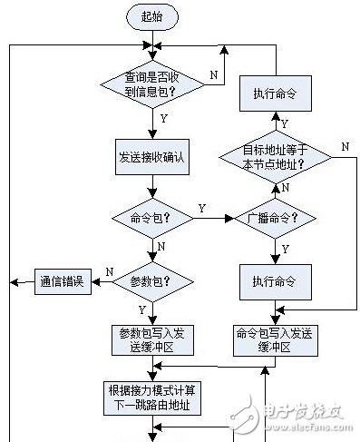
Each node on the street light sensing network is both a terminal node for command execution and state parameter collection, and a route coordination working node. In addition to receiving the packet and entering the processing flow, each node is almost in the state of the listening query for the rest of the time, checking whether the packet is received. Figure 4 shows the workflow of the LED street light sensor network node, which is a description of the process of implementing the network protocol on the node.
Conclusion
Through the detailed introduction of several parts such as network system, network protocol, network node workflow and protocol implementation, the composition of LED street light wireless sensor network is destructed, hoping to play a role in the application of LED street light wireless sensor network. . The foundation of the LED street light wireless sensor network is the point-to-point communication technology. The command information needs to cover the whole network and needs point-to-point communication technology to complete. A good network protocol is the key to building a sensor network, and a simple and feasible network. The agreement is a prerequisite for practical use. The practical application shows that the LED street light wireless sensor network constructed by the above method has good real-time performance, can work stably and reliably, and can meet the intelligent management requirements of the LED street lamp network.
Medium Voltage Power Cables includes Single Core Medium Voltage Cable, Three Cores Medium Voltage Cable. They are used for power networks, industrial plants.
Generally, Medium Voltage Cables are Copper Wire conductor, Semi-conductor Shield, XLPE insulation, Semi-conductor Shield, Steel Wire Armored or Steel Tape Armored, with PVC sheath or LSOH Sheath.
We supply lots of those Cable as per IEC 60502 and other requirements. BDK is top supplier for China Southern Power Grid.
Medium Voltage Power Cables,Medium Voltage Cable,Cable Medium Voltage,Mv Cable
Shenzhen Bendakang Cables Holding Co., Ltd , https://www.bdkcables.com