Intelligent wireless communication
This article refers to the address: http://
Intelligent wireless communication requires automatic operation, that is, the user can detect or send signals by himself without pressing any button. It is 100% independent, self-learning and adaptive in different environments, and can eliminate noise in a noisy environment. work.
The above intelligent wireless communication system has many requirements. The first requirement is small size and low cost. The solution is realized by an intelligent single-chip microcomputer. The single-chip microcomputer combines digital and analog front ends into one chip; the second requirement is economic two-way. Communication, base station command is transmitted with low frequency of 125KHz, high frequency response, and the transmission cost is gradually reduced with low frequency; the third requirement is that the communication distance is more than 2 meters, and the transponder has a high input sensitivity of about 3 millivolts; In a noisy environment, because there is a lot of noise interference in a general environment, it is very important to require a high degree of sensitivity when designing the system; in addition, the directionality of the antenna is eliminated because the control signal cannot always be sent from one direction. Especially for the unit that is carried around, the direction of transmission cannot be controlled, so the antenna XYZ in three directions is used on the transponder board, no matter which aspect the signal can be received; the battery life requirement is also required because there is Some batteries are used for the tire pressure detection system inside the car. It is impossible to turn on the power every 6 months.
Figure 1 shows an intelligent passive keyless entry control system. The illustrated system has similarities and similarities to the commonly used system. The left base station consists of a single-chip microcomputer and a high-frequency transmitter and a low-frequency transmitter and receiver. The base station sends a low frequency command of 125 KHz. When the smart receiver on the right receives the signal, it will process the signal, and the signal reaches a certain requirement to use the high frequency or low frequency as a response. The intelligent receiver has three receiving directions XYZ, which can be received regardless of the direction from which the signal is sent, and the user does not need any buttons. Such intelligent receivers can automatically receive, transmit and process signals.
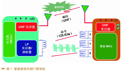
Figure 2 shows the schematic diagram of the PKE transponder. The PIC16F639 is composed of PIC16F636 and MCP2030. The MCP2032 is an analog front end. The PIC16F636 is another MCU. The combination of the PIC16F636 and the analog front end is mainly because the PIC16F636 has Keylock encryption and decryption. The function, if the user does not need encryption and decryption, you can use the 2030 analog front end and other microcontroller combinations.
Application example
There are many smart transponders used in automotive system applications, such as smart vehicle access systems, engine anti-theft locking systems (shown in Figure 3), and tire pressure monitoring systems (TPMS).
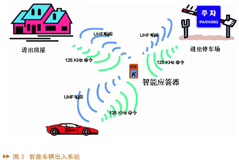
Smart PKE transponders are not only suitable for use in cars, but also in other places, such as garage doors and doors, public parking lots. If there are smart transponders in many cars, the doors will open automatically when the car is close to the parking lot.
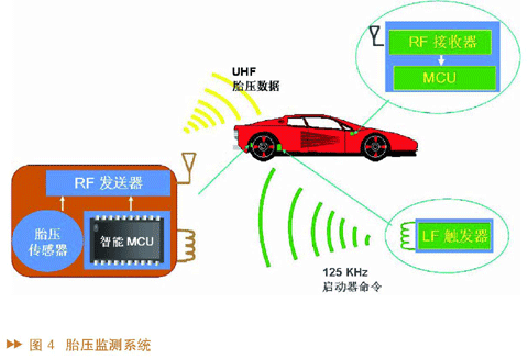
The display group of the tire pressure detection system (shown in Figure 4) is mainly composed of three units: one inside the tire, the lower left corner of the figure is composed of intelligent single chip microcomputer, tire pressure sensor and high frequency transmitter; the upper right corner is the base station, mainly It consists of a single-chip microcomputer and a high-frequency receiver; the lower right corner is a low-frequency trigger, which is usually placed close to the body part of the tire. When used, the low-frequency trigger will issue a start command to the tire unit every 3 or 4 seconds. When the signal received by the smart MCU inside the tire meets the requirements, the tire pressure sensor is told to measure the temperature and tire pressure of the tire, and then the data of the tire pressure is sent to the base station by the high frequency transmitter.
Programmable digital wake-up filter
The purpose of using the wake-up filter is mainly to reduce the operating current, thereby extending the life of the battery. In general, the digital portion remains in sleep to achieve the lowest current usage. While the analog front end keeps looking for the input signal, the analog front end will wake up the filter only when the predetermined waveform is reached, ie the input signal is required.
Intelligent Passive Keyless Entry (PKE) System Design
Figure 5 shows a transponder circuit with no battery and backup battery. In some cases, if the battery is not in good contact, the system will have no power. You can use a magnetic field to supply power for a short time, so that the transponder can still be used without a battery. Can work.
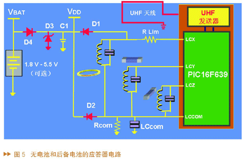
The system work requirement is that there are low-frequency wires, high-frequency transmitters, and some optional backup electronic circuits in the transponder, in addition to an intelligent microcontroller and microcontroller components; the base station system requires a low-frequency transmitter. , high-frequency receiver, antenna, microcontroller and firmware part of the microcontroller.
The two-way communication distance has some parameters, the transponder needs antenna tuning and Q, the antenna positioning uses a three-dimensional antenna, the receiving sensitivity, and the modulation depth of the output signal; the base station needs output power and receiving sensitivity.
The low frequency of the antenna design is generally 125KHz. Now the LC resonant circuit is used. The antenna type uses an air core or a ferrite core. The resonant frequency of the LC is the same as the carrier frequency of the base station. The range passive tag is about 1 meter, and the active tag is 5 meters. about. High frequencies range from 315MHz to 960MHz, the most common are 315MHz and 433MHz. The dipole wires are engraved on the PCB, the range is relatively high, the passive tag is about 5 meters, and the active tag is about 100 meters.
Figure 6 shows a formula for the relationship between magnetic flux and antenna induced voltage. Here, it is mainly to show that many factors are seen when judging the induced voltage: such as the number of turns of the coil, the surface area of ​​the contactor coil, the frequency, the receiving wire and the transmitting antenna. The angle will affect the voltage induced by the antenna.
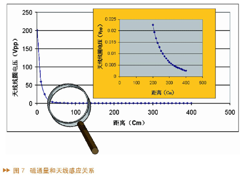
Figure 7 shows the relationship between the induced voltage and the distance of an antenna. The big picture shows that when the base station and the receiver are close together, the signal voltage is 200V, and the small picture shows the distance to 3 meters. The signal only reaches a peak of 5 millivolts, and it can be seen that the sensitivity of the signal input is critical here.
We can conclude that a smart wireless communication system requires reliable automatic operation, including intelligent two-way communication, low system cost, low frequency input high sensitivity (which is more critical), low power consumption and secure data encryption and decryption. The conclusion is that an intelligent MCU build system can meet all the requirements and therefore can be used as a reliable solution.
Fire cable includes Fire Resistant Cable, Fire Retardant Cable, Fire Alarm Cable, Mineral Insulated Cable. Those Fire Cable for installation where fire, smoke emission and toxic fumes create a potential threat to life and equipment.
Generally, Fire cable are Copper Wire conductor, Mica tape fire barrier, LSOH insulation or silicone and rubber compound insulation, with shield or not, LSOH Sheath or silicone and rubber compound Sheath
We supply lots of those Cable as per BS EN / IEC 60332-3-24, BS 4066 and other requirements.
Fire Cable,Alarm Cable,Fire Rated Cables,Vitalink Cable
Shenzhen Bendakang Cables Holding Co., Ltd , https://www.bdkcables.com