As communications and data center applications are upgraded to higher data rates to support the rapidly growing demand for Internet traffic, the performance of the SerDes reference clock is becoming increasingly important. If the reference clock jitter is too high, it can result in excessive bit error rate (BER), loss of traffic, or loss of system communication. In addition, the 56G PAM4 PHY, 100G/200G/400G Ethernet, and 100G/400G OTN require multiple frequency combinations, further increasing the complexity of timing.
To this end, Silicon Labs offers a new active clock oscillator that is driven by fourth-generation DSPLL technology to effectively solve 25/40/50/100/400Gbps timing issues. This technical article "Using High-Performance Active Clock Oscillator to Reduce Communication Application Development Risk" will detail the timing requirements for high-speed communications and data centers, and introduce Silicon Labs' market-proven clock oscillator solution to help engineers overcome Increasingly difficult high-speed network timing design challenges.
High-speed communication and data center timing requirements
Silicon Labs' latest Si54x Ultra Series active clock oscillator products are built for these demanding high-speed communications and data center applications. These high-performance active clock oscillators feature any frequency synthesis and 80 fs RMS ultra-low jitter, and are available in standard and small package size active clock oscillators. With leading jitter tolerance and frequency flexibility, the Ultra Series delivers design confidence to hardware designers while reducing product development risk.

Figure 1. Timing requirements for high-speed communications and data centers
*Note: Calculated directly according to the reference clock or transmitter eye closure specifications, in line with the original (without FEC) BER requirements, with a closed budget of 50/50 deterministic jitter/rms jitter and 33%/67% clock/transmission Device.

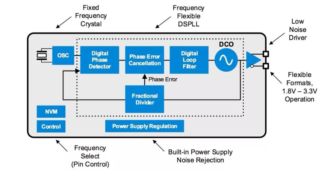
Figure 2 Ultra Series DSPLL architecture
Figure 2 shows the architecture of Silicon Labs' new Ultra Series fourth-generation DSPLL. Unlike traditional active clock oscillator technology, which requires complex batch manufacturing processes and different crystals at different frequencies, the Si54x architecture combines a simple high-quality fixed-frequency crystal with Silicon Labs' latest generation DSPLL to generate any frequency. The device can be set to a custom target frequency during the output test. With this innovative approach, the Si54x can be easily customized in batches to meet the different needs of different customers. Supporting any frequency between 200 kHz and 1.5 GHz, the Si54x Ultra Series easily supports both standard and custom frequency applications in a single product line.
Designed with industry-leading 55 nm CMOS technology, the fourth-generation DSPLL utilizes a highly digital architecture for optimal frequency flexibility and jitter performance. The input to the DSPLL phase detector is converted from an analog input to a digital input, allowing the DSPLL to operate entirely within the digital domain. This comprehensive digital approach has many advantages. First, the digitally controlled active clock oscillator (DCO) can be precisely controlled with steps less than 1 ppb to track the phase delay between the reference clock and the feedback clock. The DCO gain is small, so the circuit is less likely to be noisy than traditional analog PLLs. Second, the DSPLL supports innovative phase error cancellation circuitry that uses advanced digital signal processors to eliminate PLL noise caused by delay, nonlinearity, and temperature effects. These architectural features ensure consistent performance of the device at different processes, voltages and temperatures. As a result, Silicon Labs' fourth-generation DSPLL architecture delivers ultra-low jitter over the entire operating range.
Both frequency flexibility and ultra-low jitter
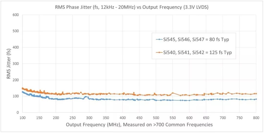
The following figure shows the comparison of the jitter performance and operating frequency and temperature of the Ultra Series. There are two performance levels available. The typical phase jitter performance of a Si545/6/7 device is 80 fs RMS (12 kHz - 20 MHz), while the typical phase jitter performance of a Si540/1/2 device is 125 fs RMS (12 kHz - 20 MHz). Due to its jitter performance, the Si54x maximizes jitter tolerance and gives design confidence to hardware customers.

Figure 3 Si54x Ultra Series XO jitter performance and frequency
To further simplify device evaluation, Silicon Labs provides an XO phase noise lookup utility that can be used to retrieve the phase noise map of the Silicon Labs active clock oscillator over more than 1000 common frequency ranges. To use this free utility, please visit:
Http://.
Integrated power supply noise control
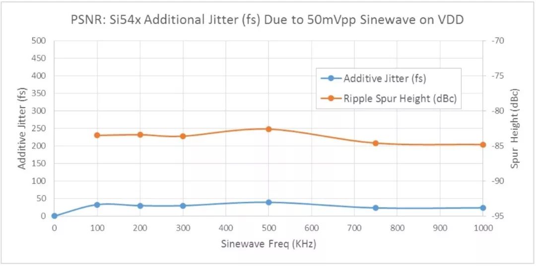
The fourth-generation DSPLL has a wide network of integrated low-dropout regulators with power supply noise rejection to ensure low-jitter operation even in noisy system environments. Another advantage of integrated power supply noise rejection is that it simplifies power supply filtering, PCB design, and layout.

Figure 4 Integrated PSNR to minimize additional jitter
Multi-frequency support
In addition to the standard single-frequency active clock oscillators, there are also dual- or quad-band active clock oscillators using Silicon Labs' fourth-generation DSPLL architecture. These devices can replace two or more discrete active clock oscillators with one IC, minimizing BOM cost and complexity. Multi-frequency active clock oscillators have several advantages:
Support multi-protocol SerDes with a single device
Simplified setup/hold time test
Frequency tolerance (eg 156.25 MHz + 50 ppm, 156.25 MHz, 156.25 MHz -50 ppm)
Simplify prototyping. Test a new SerDes and ASIC with multiple reference clocks using a multi-frequency active clock oscillator. Converted to a fixed single frequency active clock oscillator after the final frequency is selected
Single power supply
Silicon Labs' Ultra Series Active Clock Oscillator has a highly flexible output driver that can be factory-customized to support any common signal format: LVDS, LVPECL, HCSL, CML, CMOS, and dual CMOS. In addition, the output driver supports a wide range of supply voltages. A single Si54x device can support an operating voltage range of 1.8V-3.3V, replacing multiple active clock oscillators with fixed voltages of 1.8V, 2.5V, and 3.3V using only a single part number active clock oscillator.
Get samples quickly
Silicon Labs offers a web-based utility that creates a custom active clock oscillator in less than a minute. Once the part number has been created, an order can be placed through an authorized distributor of Silicon Labs or the Silicon Labs website. Samples are usually shipped within 1-2 weeks of order placement. This process greatly simplifies the purchase of active clock oscillators and is the perfect choice for prototyping and NPI trial production of fast acquisition equipment.
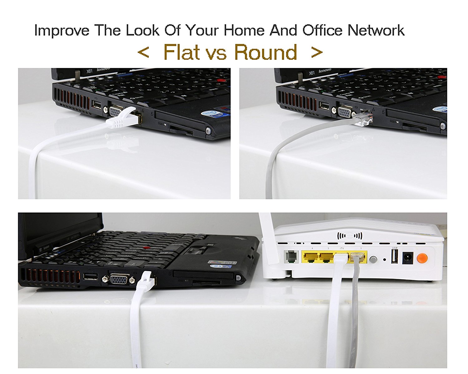
CAT7 Flat Patch Cable, A Flat cable design helps improve the look of your home or office. Flat cables are super flexible and can be run under the carpet or bent through corners or into desks.

A double stranded DU line from the latest BAI in ISO/IEC 11801 class 7 /F standard 1. It is mainly used for the application and development of ten thousand ZHI bit Ethernet DAO network technology.CAT7 is no longer an UNshielded twisted pair , but a shielded twisted pair, thus providing a combined attenuation to crossposition ratio of at least 500MHZ and an overall bandwidth of 600MHZ, more than twice that of CAT6 and Super Six lines, with a transmission rate of up to 10Gbps.In the CAT7 Ethernet Cable, each pair has a shield layer, and four pairs of wires together have a common shield layer.
In terms of physical structure, the additional shielding layer makes the CAT7 have a larger diameter.Another important difference is its ability to connect hardware. The parameters of the cat7 of systems require that all pairs of wires provide at least 60DB of integrated proximal winding at 600MHZ.The cat5e systems only require 43DB at 100MHZ and 46DB at 250MHZ for the CAT6.
Cat7 Flat Ethernet Cable,Nylon Braided Ethernet Cable,Cat7 Flat Cable,Nylon Braided Network Cable Cat7
Shenzhen Kingwire Electronics Co., Ltd. , https://www.kingwires.com