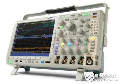
Triggering is one of the biggest features that distinguishes a digital oscilloscope from an analog oscilloscope The trigger function of the digital oscilloscope is very rich. The trigger setting allows the user to see the signal before the trigger and the signal after the trigger. For the analysis of high-speed signals, it is rare to talk about triggering, because it is usually a waveform that captures for a long time and then performs eye diagram and jitter analysis. Triggering may be applied more frequently for measurements of low speed signals, as low speed signals typically encounter very weird signals that need to be isolated by triggering.
Trigger level on the oscilloscopeIntuitively, the trigger level is the signal that causes the oscilloscope to scan. Generally, the oscilloscope is automatically triggered when it is turned on. It is convenient when measuring continuous repeated signals. But to measure the data of a specific location, you need to trigger it accurately. The trigger level format is further divided into rising edge, falling edge, and some other signals, such as I2C serial port data, for precise triggering, which is triggered by data characteristics. There is also the use of an external trigger, you can choose a different channel to trigger the channel. For example, if you debug the MCU, you can program an IO to output a level before a specific action. After the action is resumed, input this pulse into a channel as a trigger signal (set the trigger to NORM mode). The channel acquired at this time is only triggered at this trigger. The data is stable and displayed before and after the position, and will not run away, and the part of the acquisition channel signal corresponding to the triggered pulse is the precise range to be observed, which is convenient for analysis.

Trigger level adjustment, also known as sync adjustment, causes the sweep to be synchronized with the signal under test. The level adjustment knob adjusts the trigger level of the trigger signal. The scan is triggered as soon as the trigger signal exceeds the trigger level set by the knob. Rotate the knob clockwise to raise the trigger level; turn the knob counterclockwise to decrease the trigger level. When the level knob is adjusted to the level lock position, the trigger level is automatically maintained within the amplitude of the trigger signal, and a level adjustment is required to generate a stable trigger. When the signal waveform is complicated and the level knob cannot be used for stable triggering, use the Hold Off knob to adjust the holdoff time of the waveform (scan pause time) to synchronize the scan with the waveform.
The polarity switch is used to select the polarity of the trigger signal. When dialed in the "+" position, a trigger is generated when the trigger signal exceeds the trigger level in the direction of signal increase. When dialed in the "-" position, the trigger is generated when the trigger signal exceeds the trigger level in the direction of signal reduction. The trigger polarity and the trigger level together determine the trigger point of the trigger signal.
Gold Finger Slot Connector,Dual Contact Gold Finger Slot Connector,High Current Slot Power Connector,Gold Finger Slot Power Connector
Dongguan SOLEPIN Electronics Co., Ltd , https://www.wentae.com