Simple Network Management Protocol (SNMP) is the framework for the underlying network management provided by the network management system. It is used in a wide range of applications, including many types of network equipment, software and systems. The development of the SNMP protocol to the current third edition has become a very mature network management protocol [1]. However, due to the different support procedures for each device, the mature network management framework for SNMP is still very rare [2]. In terms of SNMP support, Cisco is at the forefront [3]. In addition to fully supporting the definition of MIB-2 in RFC1213, RMON in RFC2819 and RFC2021 is also supported in some devices. Based on Cisco's mainstream, developing a "scalable" SNMP-based network management framework has become very realistic.
1 Development platform and architecture selection The C# language of the .NET platform has rich language features. For example, Lambda expressions (used multiple times in the Auto-Topology control and software framework) can significantly improve development efficiency, and the official development environment supporting C# is recognized. An integrated development environment that is more conducive to team collaboration. Furthermore, C# anonymous objects, object initializers, closures support LINQ and other features that are good for DSL performance, coupled with good asynchronous programming support, make C# the preferred language. Naturally, the preferred platform is .NET.
The two basic issues that software must face are "universality" and "scalability." The so-called versatility is the basic function that can be used in most network environments; the so-called scalability is the ability to give full play to the unique functions of unique devices under the premise of ensuring universality. This makes the design of the universal framework more difficult.
How to make network management tasks fully simplified is a key consideration. The way software works will affect the behavior of operations. C/S structure or purely single software will undoubtedly have more powerful graphics capabilities, while B/S structure It has a better performance in terms of scalability and cross-platform. A more compromised and cost-effective option is to implement versatility and cross-platform at the framework level and separate the presentation layer into different solutions. In the end, the software uses the same way that ordinary software works.
Although you can develop the underlying communication class library of SNMP to support the whole project, considering the factors such as the development cycle, you should seek a better open source component to undertake the basic communication. There are two open source components to choose from: SnmpSharpNet and SharpSnmpLib. After carefully studying the two components, SharpSnmpLib was updated more frequently and the code was more maintenance-friendly, so SharpSnmpLib was chosen to support development.
Since the SNMP protocol supports different conditions on different devices, it is very challenging to require some common functions of the software to be compatible with most devices. Common network management tasks are basically based on extensions based on topology maps. Therefore, no matter how different devices are and how complex the protocol support is, automatic network topology discovery is an indispensable core function. How to implement extended functions based on compatibility with common devices has become a key issue for research.
Rather than being compatible, it's better to understand that it is implemented using only the features that most hardware can support. An obvious solution is to use only the MIB-2 functional group defined in RFC1213. MIB-2 defines objects that are frequently used in network management and is supported by most devices. If you only use the functions defined in MIB-2 to support the core functions of the software, then the software and hardware compatibility issues will naturally be much less.
2.1.2 Obtaining Network Topology Through SNMP
There is no direct access to the topology object in the related functions of the SNMP protocol. In some private MIBs (such as related objects related to CDP in Cisco), there are such direct functions, but the network environment and equipment are demanding (CDP protocol is only in pure Cisco). Useful in the network, although some non-Ciscos start to support CDP, but the number is very small [4], so this is not a universal solution.
In order to maintain the compatibility of the device and the network, it is mentioned that the "conservative" object should be used to implement the core functions, so the automatic discovery of the topology map can only find the corresponding solution from MIB-2. Network topology, as its name suggests, is the logical relationship between network devices, so reflected in the network technology, the most direct correspondence is the routing table. However, there is only a relationship between network devices in the routing table. The PC information supporting SNMP is not in the routing table. How to solve the PC discovery that supports SNMP? One solution is to look up the "address translation table" in the network device, which has the IP information of the PC. By performing SNMP tests on these PCs one by one, the entire SNMP network can be fully supported [5]. In addition, you need to know the IP of the device's own interface, which is defined in the MIB-2 IP functional group (1.3.6.1.2.1.4).
After the mechanism of the topology map is determined, another difficulty is how to arrange each device and related lines on the screen. Since the only relationship between devices is the mutual link, and no data related to the physical structure is available, it is very difficult to draw a topology map identical or similar to the physical structure completely through software. Very few materials and papers [6].
The distribution of topological maps is an academic problem. The ring weight distribution is only used as a theoretical attempt. In order to have better theoretical support in the future, the layout algorithm can be flexibly modified. The software adopts “strategy mode†in the development process. The layout algorithm is abstracted and easy to replace.
The domain model records key concepts and vocabularies in a system, shows the relationships between the main entities in the system, and identifies their important methods and attributes. For an SNMP application system, the main domain model is the SNMP entity. Another extension function is the “management†of network devices, which involves asset evaluation, device statistics, maintenance management and other related applications. In other words, how to match the information obtained by the software with the actual devices is One aspect of software that needs to be addressed.
3 Overall description and frame design 3.1 System Core The core issues involved in system implementation are as follows:
(1) How to obtain and draw the topology map and adjust the topology style reasonably;
(2) Reasonable scheduling of the synchronization engine and information storage structure;
(3) Reasonable classification of functions and analysis, organization and modeling of relevant OIDs;
(4) Selection of basic building blocks.
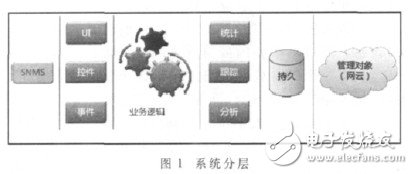
Because the system adopts layered development and scalability, the software is logically divided into four layers—the persistence layer, the base layer, the business layer, and the presentation layer. The basic working mode is shown in Figure 1.

The storage model provides a mechanism for persistence for "device management" and related extended applications, and provides a basis for statistics, analysis, and other requirements for querying and comparing historical data.
For the choice of database, from the cost point of view, there are Microsoft SQL Server Express, Microsoft SQL CE, MongoDB, NoSQL to choose from, and from the deployment considerations MongoDB, part of NoSQL, Microsoft SQL CE can choose, and finally from the performance point of view, Microsoft SQL CE is used to support the storage model.
After the persistent data can be valid in a relatively fixed time, on this basis, the functions of statistics, tracking, analysis, etc. will be much faster, and the load on the network will be significantly reduced.
The main logic of the system interacting with the SNMP network depends on the SNMP object data transmitted by the SNMP protocol. The SNMP object depends on the related MIB to describe its characteristics and structure. The domain logic required by the software is mainly focused on the operation of SNMP entities, but the operation of SNMP is not program friendly. In other words, SNMP cannot be manipulated by the smooth API to be used by the software. So you need to design a domain logic that turns the specific domain of SNMP into a program-friendly domain. Consider the domain transformation shown in Figure 2.

The operating primitives of SNMP are translated into corresponding programming concepts, transforming the realm of SNMP into the realm of programming. This laid the foundation for AOP programming and the expansion of the storage model.
The sorting algorithm of the topology map is called "ring weight distribution", mainly because the concept of "weight" of the device in the network is introduced. Since the main purpose of the layout is to enable the main devices to be distributed and properly positioned on the screen, the algorithm of the topology layout first finds the devices with the highest "weight" and sorts the devices according to this order. The main steps of the algorithm are:
(1) Devices are sorted by "weight". The system is mainly oriented to routing and switching equipment, so the most sensitive information to the topology map is the "routing" information. If a device core has a higher number of routes than other devices, the device is a so-called "core device."
(2) The highest weight priority positioning. Step (1) has determined the most core devices and the device groupings sorted by "weight". The most core equipment is the first group, which will be centered on the center of the screen and evenly distributed on a circle of a certain radius. The radius is determined by the number of devices to be positioned, and the larger the number, the larger the radius value. When the positioning of these devices is completed, the angle of the device at the center of the screen (∠θ) is determined, which will be used as the basis for the next step.
(3) "Satellite" equipment layout. The equipment connected to the core equipment is classified as the satellite equipment of the core equipment. The specific distribution algorithm of the "satellite" equipment is as follows:
Assuming there are n core devices, the satellite devices of each core device can only be distributed in a 360/n sector range, as shown in Figure 3.

In Figure 3, there are three core devices, which are divided into three sectoral regions: A, B, and C. Taking R2 as an example, its three satellite devices are distributed in the B region, and are evenly distributed according to ∠θ in the B sector. The radius will be corrected accordingly with the number of satellite devices.
(4) Draw a link connection. The connections in the core device area allow for interleaving, as the connections in this part are almost impossible to cross. Since the distribution is ring-based, even if the wires are staggered, the problem will not be serious. The connection of the satellite equipment is mainly for the previous device. In this case, it can be directly connected. If there is a connection between the satellite devices, the layout of the satellite device can be adjusted slightly, and the connection is not excessive. cross.
At this point, if there is a connection between the x device and the z device, some small adjustments will be made to the position of the x or z according to the space on the screen, so that the connection between x and z is more reasonable.
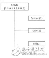
For the convenience of naming, the network monitoring system based on the simple network management protocol is referred to as SNMS. According to the MIB naming scheme, a node named Tute (888) is customized under the 1.3.6.1.4.1 node, and the SNMS (1) node is defined under the node.
After defining the object identifier in the MIB, it is necessary to divide the objects that the software can only deal with and need to be managed. Here, the SNMS system is divided into three parts: system, user and file, which are respectively defined as system (1). ), user(2) and file(3), as shown in Figure 4.

In order to enable the software to be notified when an event occurs on the device, in the context of SNMP, it means a mechanism for receiving traps. The device sends traps according to the receiving objects configured by the device itself, in the range of events that can be supported by the device.
Different versions of the SNMP protocol correspond to different Trap formats. However, for SNMS itself, these versions of Trap do not make sense. All that software needs is the necessary identification and the meaning of the corresponding identifier. So a mechanism is needed to unify these versions of the Trap.
The way the software is used is to use the middle tier to proxy. Use TrapMonitor to listen to all versions of the Trap and finally touch through different processes.
Sends a TrapComing event and passes in the generated TrapInfoEventArgs for use by subscribers.
4.3.2 Translation of Trap Information
Trap contains hundreds of pieces of information, and it would be a very time consuming and expensive project to parse its information by software. Moreover, due to the scalability of SNMP itself, software cannot predict the new Trap definitions that follow, so consider a mechanism that models Trap and abstracts its core into a scalable and configurable mode.
This mechanism makes the software easy to adapt to different scenarios and is also easy to deploy. The software itself also integrates the configuration function of the Trap information to avoid manual contact with XML files.
How to filter out useful Trap information is critical, which is determined by the "management" nature of the system. The system decided to adopt a network ACL-like approach and proposed a whitelist and blacklist filtering mode. Similar to Trap information translation, the system also uses an XML-based approach to save filtering rules in a more flexible deployment XML file. The whitelist is a trap that matches the rules in the list. The blacklist is the trap that does not match the rule after all traps arrive.
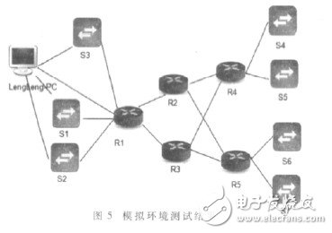
5 Testing and deployment The final test environment used the most commonly used network equipment - medium-routed data exchange network. The environment uses five Cisco 7200 routers to build with seven Cisco 3640 switches, and configures the relevant routing protocols. Finally, SNMP and Trap functions are enabled.
The system performs topology discovery on the medium-sized routing data exchange network environment. The test results are shown in Figure 5.

Figure 6 is a network topology obtained by performing system testing in a real network environment.

As an upper-layer application software system based on SNMP, in addition to implementing the core topology discovery mechanism and topology layout, the software continuously improves the software framework to adapt to different upper layer development. The ideal evolution of software is to make an SNMP-based infrastructure on which to continuously expand applications. Due to the maturity of the SNMP protocol itself, this framework of requirements has great potential.
xcool vape enjoy free, Disposable Vape Pen brand
Xcool vapor disposable vape pen, xcool vapor hnb, xcool vapor cbd
Shenzhen Xcool Vapor Technology Co.,Ltd , http://www.xcoolvapor.com