A major challenge in automotive design is to protect electronic components—such as control units, sensors, and entertainment systems—from damaging reverse voltages, voltage transients, electrostatic discharge (ESD), and noise that appear on the power line. interference. Rectifiers are an ideal solution for automotive electrical power line protection. There are several important parameters to consider for these applications, including forward current, repeated reverse voltage, forward surge current, and melt speed.
Automotive electronic equipment test conditions and parameters in the applicationThe basic circuit for polarity protection is shown in Figure 1. Circuit (A) provides only polarity protection, while circuit (B) provides load dump suppression in addition to polarity protection.
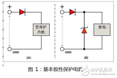
The following is a definition of the main parameters to consider when selecting a power line polarity protection diode for automotive applications.
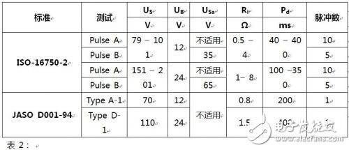
Maximum Repeated Reverse Voltage (VRRM)The maximum repeating reverse voltage is the maximum voltage that the diode can withstand in reverse bias mode. In reverse bias mode, leakage current through the diode creates heat in the diode junction and causes thermal runaway. The tests simulating this condition include ISO-7637-2 pulse 1 and 3a in the United States and JAS D001-94 standard type B and E.Each in Japan. The peak voltages of these tests are shown in the following table.

According to the above test conditions, the VRRM for the diode for power line protection should be 300 V - 400V for the 12V power line and 600V for the 24V power line.
Forward current (IF(AV))The forward current specified in the product description usually refers to the maximum average forward current that the diode can withstand in the forward bias state under the thermal limit of the package. This parameter is related to the current consumption of the circuit in operation.
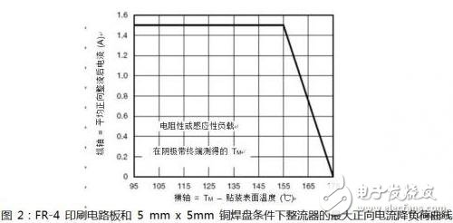
The forward current capability varies with the junction temperature of the diode, as shown in Figure 2. Other relevant parameters include thermal resistance (represented by symbols such as RqJC, RqJA, RqJL, and RqJM).
Forward Surge Current (IFSM) The forward surge current specified in the product description refers to the maximum peak current that the diode can withstand in the forward bias state within the specified time and pulse conditions. This rating is limited by the heat capacity of the diode.
The forward surge current specification is related to two main operations, and the ISO-16750-2 and JASO D001-94 automotive standards contain tests that simulate these two operations. The first operation is to protect the circuit from high currents that occur during load dump conditions. The test that simulates the second operation is ISO-7637-2 Pulse 2a and 3b, which consist of a 50 ms and 100 ms pulse width with 2Ω and 50Ω line impedance, respectively. This is a relatively small energy value compared to the forward surge current under load dump test conditions.
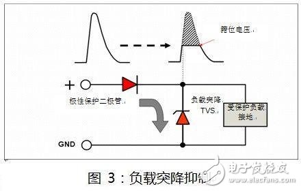
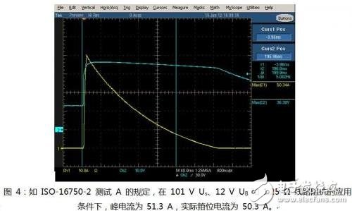
Simulation tests for load dump suppression include ISO-16750-2 test A and B, JASO standard type A and D and other tests.
In this case, high inrush current flows through the polarity protection diode and requires a sufficiently high forward surge capability to avoid failure. The following formula can be used to estimate the inrush current value in the load dump suppression test:
Ipeak = ( Vpeak– VFd - Vclamping) / (Ri + Rzd)
Vpeak: Surge voltage Vclamping: Clamp voltage VFd: Forward voltage drop of the polarity protection diode Ri: Line resistance Rzd: Resistance of the clamp component
Electrostatic discharge can affect the operational stability of the on-board electronic module and the reliability during its service life.
ISO-10605 and JASO Standard 5.8 specify test conditions for this parameter.
Non-repetitive avalanche energy (EAS)The non-repetitive avalanche energy of a diode is the maximum energy that a diode can absorb in a biased state in order to prevent the circuit from being subjected to an induced transient kickback voltage from the motor and solenoid or by inducing a high reverse voltage. There are currently no automotive standards for this parameter.
Temperature conditions for automotive electronic systems and components JASO sets its operating temperature range from – 40oC to + 100oC depending on the location of the automotive electronics system and components, such as the trunk, engine and other locations.
When designing an electronic unit for a car, it is considered to protect the electronic unit from the penetration or induced transient energy from the sensing unit and the impact of the reverse electrical connection. Transient energy is generated by spark plugs and motors that drive wipers, brakes, door locks, and other components. Also consider electrostatic discharge from people and car interiors.
Portable Speaker,Speaker Receiver,Outdoor Speakers,Wireless Speakers
GUANGZHOU LIWEI ELECTRONICS CO.,LTD , https://www.gdliwei.com