Rotary piston flowmeter is a volumetric flowmeter. It has reliable operation, high measurement accuracy and low pressure loss. When the viscosity of the medium is greater than 50cp, the viscosity change has no effect on the accuracy. It is suitable for the measurement of instantaneous and cumulative flow rates of liquids without solid particulate media. After the instrument has been used for a period of time, it has been repaired several times, and the calibration data confirms that many flow meters have been out of tolerance. Below we analyze the measurement principle and structural composition to analyze the root cause and correction method.
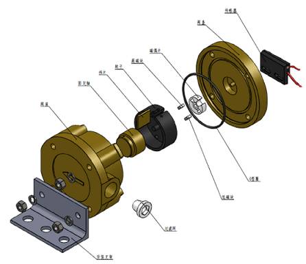
Analysis of measurement principle
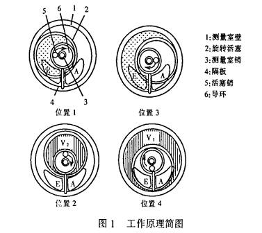
The rotary piston flowmeter is based on the principle of continuous filling and emptying of the measuring chamber (V1+V2) (see Figure 1). The measuring mechanism consists of a measuring chamber with a cover, a rotating piston and a partition. The slotted piston has two upper and lower piston pins, and the partition plate is radially installed between the inlet and the outlet, and the measuring chamber pin is concentric with the guide ring. During the measurement, the slot of the slotted piston moves linearly along the diaphragm, and the piston pin moves in a circular motion along the guide ring. Since the volume of the measurement chamber is fixed, the instantaneous flow rate of the medium flowing through the measurement chamber is only related to the speed at which the rotary piston rotates, and the cumulative amount is related to the number of revolutions of the rotary piston.
Instantaneous flow rate (Q)=(V1 + V2) Rotational speed (V) Cumulative flow rate (Q)=(V1 + V2) Number of revolutions (n)
From the measurement principle we can see whether the measurement is accurate, whether it meets or meets the accuracy requirement, mainly depends on whether the volume of the measurement chamber changes. As long as the volume is constant, measurement errors are not easy to produce. That is, the root cause of the measurement error is the change in the volume of the measurement chamber.
Measurement error generation and correction
1. Errors and corrections caused by changes in the customer volume in the measurement room
During the use of the rotary piston flowmeter, due to the change of the pressure in the process pipeline, the instantaneous rotational speed of the rotary piston is too large, causing the impact of the piston notch on the partition plate, and the diaphragm is bent. During the inspection of this type of watch, it was found that the failure caused by the bending or even the fracture of the partition plate could not be rotated according to the original movement track when the rotary piston was rotated, causing serious wear on the inner wall and the bottom surface of the measuring chamber, the upper and lower end faces of the piston, and the inner and outer walls. Even scratches and grooves appear. In this case, it is necessary to grind the measuring chamber and the piston after replacing the diaphragm, so that the rotating piston can rotate freely in the measuring chamber and re-measure. However, after multiple inspections, the volume of the measurement chamber will change (see Figure 2).
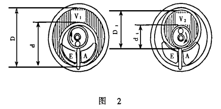
Before grinding: V = (V1 + V2) = [(D2 - d2) + (D12 - d12)]
H—measurement chamber depth (height);
V—total volume; V1—outer volume;
V2 - the inner volume.
After grinding, the following dimensions will change.
D↗, D1↗ (increase), d↘, d1↘ (decrease), then
V' = (V1 + V2) = [(D2 - d2) + (D12 - d12] + ΔV = V + △V
V'—the total volume after grinding; ΔV—the amount of volume change before and after grinding.
If the volume flow rates corresponding to V and V' are Q and Q', respectively, the reference error of the table is:

With the increase of inspection and grinding times, the δ value will become more and more too much, exceeding the accuracy level range of the watch, so that the measurement accuracy can not meet the needs of process production. In order to regain high measurement accuracy and restore the accuracy of its measurement, this measurement error can be corrected in two ways to meet the accuracy requirements.
(1) Correction is performed by replacing the paired gears with the calibration data after inspection.
As we all know, many flow measuring instrument signaling mechanisms are transmitted by a gear mechanism. The gear ratio of the gear determines the proportional relationship between the indicating mechanism and the measuring mechanism. We are using this proportional relationship to achieve the purpose of correction.
For example: a rotary piston flowmeter with an accuracy of 0.5, after repeated inspection and grinding, recalibration, the calibration error value is -1.27%. Now correct the method of replacing the paired gears. The steps are as follows:
a. Disassemble the shifting gear portion of the development mechanism, remove the shifting gear, and read the marking on the gear. If the measuring mechanism gear is marked "1-74", the indicating mechanism gear is marked "1-125".
b. Check the indication error of the original paired gear that has been compensated by the comparison table is 0.29%, and then calculate the actual error of the flowmeter.
Actual error = compensated indication error + calibration error = 0.29% + (-1.27%) = -0.98%
c. Check the paired gear with the compensation value of -0.98% according to Table 2. The measuring mechanism gear is marked as “1-60â€, the indicating mechanism gear is marked “1-110â€, and the matching gear with the mark is loaded. And recalibrate to achieve the accuracy requirements.
(2) Correction is performed by multiplying the coefficient k.
At present, many factories use instrument systems such as distribution systems and KMM digital regulators. These instrumentation systems have the function of adjusting and modifying the coefficients of variable parameters. We use this coefficient adjustment method to achieve the correction of the error.
For example, a rotary piston flowmeter has an accuracy of 0.5 and a range of 0.6 to 6 m3/h. After repeated inspections and grinding, the relative error of the indication is re-calibrated to -1.05%. Based on the data given, Table 3 and Figure 3 are obtained.
table 3
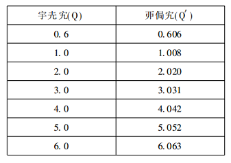
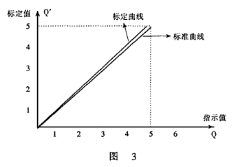
According to Table 3 and Figure 3, we can see that:
Before the calibration:
Ratio coefficient (k) = t ɡ α = calibration value / indication value = 1
Post-inspection calibration:
Ratio coefficient (k') = tgα'=

According to the calculated ratio coefficient, in the control loop of the distributed system, or in the KMM regulator variable parameter, the measured signal from the field is corrected by the configuration, and the actual indicated value and the accumulated value are obtained.
Actual indication value = measurement indication value (PV value) × ratio factor (k'), ie:
Q' = Q·K'
2, the error and correction caused by the change of medium temperature caused by the change of medium density
It is well known that many volume flow meters have the effect of temperature on the accuracy of the measured flow, which can be overcome to the greatest extent by compensation, selection and other methods. However, many production facilities, especially chemical plants, have higher flow requirements, and chemical reactions consider mass flow rather than volume flow. The relationship between the mass flow rate (M) and the volume flow rate (Q) is: M = Ï Â· Q (Ï is the medium density). If the volumetric flow rate is constant, if the density of the fluid medium changes, the mass flow rate will follow. change.
For liquid media, pressure has little effect on density and can be ignored. But the effect of temperature on density cannot be ignored. In order to solve the purpose of measuring the mass flow rate of the rotary piston flowmeter, we have made some attempts. Below we take ethylene glycol in chemical raw materials as an example, according to the relationship between temperature and density of ethylene glycol medium, the influence of temperature of ethylene glycol fermentation on volume flow measurement is discussed.
For example, a rotary piston flowmeter has an accuracy of 0.5, a measurement range of 0.6 to 6 m3/h, a process requirement setting flow rate of 2.5 m3/h, and a medium temperature of 180 °C. If the temperature becomes 165 ° C, the volume flow will change under the condition that the mass flow rate is constant, and the flow indication value deviates from the given value, and the indication value is out of tolerance.
The volume flow rate at 180 ° C is 2.5 m 3 / h, and the ethylene glycol density is 986 kg / m 3 , then the mass flow rate controlled at this time is:
M = Ï·Q = 986×2.5 = 2465kg/h
At 165 ° C, if the mass flow to be controlled is 2465 kg / h. At this time, the density of ethylene glycol is 1000kg/h, and the corresponding volume flow rate is:

Then, due to the change in temperature, the error caused by the volume flow is obvious under the condition that the mass flow rate is constant.

Indication relative error =

Since this error is caused by external factors (temperature) of the rotary piston flowmeter and has a large influence on the process, the chemical reaction is only related to the mass (or mole number) of the substance, and is independent of the volume of the substance. Therefore, to ensure that the mass flow rate of the medium does not change, when the temperature changes greatly, the error correction of the volume flow must be considered, and this correction cannot be corrected by the rotary piston flowmeter itself, nor can it be replaced by It is corrected by the method of multiplying the gear or by multiplying the coefficient k, and only by changing the set value of the volume flow. In the above example, if the flow rate is changed from 2.5m3/h to 2.465m3/h, the purpose of the correction can be achieved to meet the measurement requirements of the process.
In summary, we briefly discuss the measurement error and correction method of the rotary piston flowmeter, and make some analysis on how to overcome the error caused by the volume and temperature changes. The method is simple and easy to implement, and is beneficial to solve the problem of degradation of the table.
Guangzhou Bolei Electronic Technology Co., Ltd. , https://www.nzpal.com