At the industrial communication site, engineers are most worried about the transient overvoltage and overcurrent generated by the communication network due to the surge, which causes the bus communication network to send wrong signals or even system paralysis. To avoid this kind of accident, How to protect in the early design? This article will be announced for you.
1 Introduction to SurgeAt industrial communication sites, lightning overvoltages, lightning induced thunder surges, and power system (especially with very heavy inductive loads) caused by switching switches, transient overvoltages caused by these surges The flow, which leads to the data bus communication network, and even the component sending out the wrong signal, will bring great losses to the user. Now lightning protection, anti-surge and over-voltage protection are all factors that must be considered in bus design. Today, Xiaobian will talk to you about the common bus anti-surge protection.
There are two types of surge protection, one is common mode and one differential mode. Surge generated during lightning or high current switching is generally common mode. Surge in the form of differential mode is often caused by high voltage lines in the vicinity of the data cable, and poor insulation between the data cable and the high voltage line, although the differential mode ratio The common mode produces much less voltage and current, but it does not last as long as the common mode, but it will persist for a long time in the data communication network. The nominal withstand voltage of an optocoupler or a magnetically coupled device is the common mode, which is the withstand voltage between the front end and the back end. If this withstand voltage is exceeded, the front end and the back end are burned together; the components will not be rated for the withstand voltage of the differential mode, and the differential mode withstand voltage is determined by the design of the circuit. The differential mode voltage exceeds the tolerance of the circuit, and the front end burns out. The end will not burn out.
2 conventional surge protection program - discrete solutionSurge prevention circuits are usually divided into isolation methods and evasion methods. The isolation method uses an optocoupler or a magnetic coupler to isolate the input and output signals. As long as the amplitude of the voltage generated by the surge does not exceed the nominal value of the device, the optocoupler or magnetic coupling will not be damaged, even if the surge voltage Long-term presence does not cause damage to isolated equipment. This type of isolation can only suppress surges in the common mode and cannot suppress surges in the form of differential modes. (The surge mentioned here is mainly caused by lightning surges caused by lightning strikes, surges in the circuit system, etc., and direct lightning is not within the scope of discussion).
The evasive method is that the ground of the main equipment is connected to form a single point grounding. Once a surge occurs, the surge energy can be safely transferred. In addition, it is necessary to add some devices to suppress the surge. A device capable of discharging a harmful current generated by a surge into a ground loop before reaching a data port, mainly having a Tvs tube, a varistor, and a gas discharge tube, each having a clamping voltage, once the clamp is exceeded At the voltage, the device creates a low impedance between the junctions, which diverts harmful currents.
If the isolation method and the evasion method are combined, the system can be better protected. The circumvention device can suppress the surge protection isolation device on the one hand, and can also suppress the differential mode surge generated on the bus. The isolation device rejects common mode surges and protects the host device. The two complement each other to better protect the bus device.
For example, CAN interface protection is generally applied to the transceiver plus isolation protection devices, such as optocouplers, magnetic couplings and so on. For the convenience of interface design, we can use the integrated transceiver module, and the self-built circuit ratio, easy to use, simplify the circuit, and the environment adaptability is stronger. This kind of isolation module anti-common mode surge design is more common and will not be repeated. Here we focus on ways to increase surge protection in differential mode. Commonly used circumvention devices include GDT, TVS, and common mode inductors. As shown in Figure 1, the GDT is placed at the forefront of the interface to provide first-level lightning surge protection. When lightning strikes and surges occur, the GDT instantaneously reaches a low-resistance state, providing a bleed-out channel for instantaneous large currents, and clamping the voltage between CAN_H and CAN_L within a range of twenty-five volts. The back-end TVS provides second-level surge protection, and specific specifications can be selected according to requirements.

Figure 1 CAN interface circuit with increased surge mode form surge function
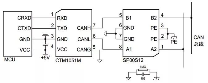
3 efficient surge protection program - module solutionAlthough the interface circuit shown in the above figure can provide effective protection, it needs to introduce more electronic devices, which means that the interface circuit will occupy more PCB space. If the device parameters are not properly selected, it will cause EMC problems. Is there a better way? Zhiyuan Electronics has designed a professional signal surge suppressor SP00S12 for its small partners. This small-volume module uses potting material combined with Zhiyuan electronic isolation module to make the circuit easily meet the surge level requirements of IEC61000-4-5 ±4KV. It can be used in various signal transmission systems to suppress harmful signals such as lightning strikes, surges and overvoltages, and protect the signal ports of equipments. It is very suitable for surge protection in communication fields such as CAN and RS-485. The details are as follows:

Figure 2 CAN bus module anti-surge application circuit
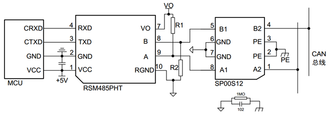
For the same reason, if the SP00S12 is used in the RSM485PHT serial communication, the signal port of the SP00S12 is connected to the differential signal ports A and B of the RSM485PHT module, so that the 485 communication port can meet the IEC61000-4-5 ±4KV surge level requirement.

Figure 3 485 module anti-surge application circuit
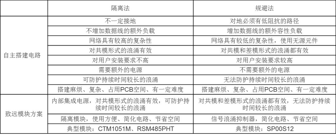
4 program summary comparisonTo sum up, the characteristics of each method are basically like this:
Table 1 Comparison of program characteristics

For the surge protection equipment for electronic and electrical equipment, it has long been available. IEC 61000-4-5 specifies the immunity requirements, experimental methods and recommended experimental range of equipment for unipolar surges caused by switching and lightning transient overvoltages. The standard specifies a consistent experimental method to evaluate the immunity of equipment and systems to specified objects. The goal is to establish a common benchmark to evaluate the performance of electrical and electronic equipment in the event of a surge.
Next, do a surge immunity test to check whether the surge suppressor meets the IEC61000-4-5±4KV protection requirements. The test configuration is tested according to the unshielded symmetrical communication line in IEC61000-4-5. The specific test circuit is as follows. Figure 1 shows. Different levels of surge voltage are applied to the surge suppressor during the test, and the voltage waveform is measured at the signal input and output terminals.

Figure 4 Common mode surge immunity test
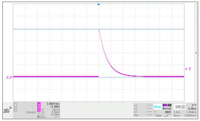
Taking the common mode surge test as an example, a 4KV, 1.2/50μs surge voltage as shown in Figure 2(a) is applied to the A2 and B2 terminals of the SP00S12 surge suppressor, and the surge voltage is tested at the output terminals A1 and B1. As shown in Figure 2(b), the surge voltage has been reduced to 17.1V.

Figure 5 Input surge voltage waveform 3.94KV

Figure 6 Waveform suppressor output waveform 17.1V
ZGAR bar 4000 Puffs
ZGAR electronic cigarette uses high-tech R&D, food grade disposable pod device and high-quality raw material. All package designs are Original IP. Our designer team is from Hong Kong. We have very high requirements for product quality, flavors taste and packaging design. The E-liquid is imported, materials are food grade, and assembly plant is medical-grade dust-free workshops.
Our products include disposable e-cigarettes, rechargeable e-cigarettes, rechargreable disposable vape pen, and various of flavors of cigarette cartridges. From 600puffs to 5000puffs, ZGAR bar Disposable offer high-tech R&D, E-cigarette improves battery capacity, We offer various of flavors and support customization. And printing designs can be customized. We have our own professional team and competitive quotations for any OEM or ODM works.
We supply OEM rechargeable disposable vape pen,OEM disposable electronic cigarette,ODM disposable vape pen,ODM disposable electronic cigarette,OEM/ODM vape pen e-cigarette,OEM/ODM atomizer device.

ZGAR bar 4000 Puffs Disposable Vape, bar 4000puffs,ZGAR bar 4000 Puffs disposable,ZGAR bar 4000 Puffs,ZGAR bar 4000 Puffs OEM/ODM disposable vape pen atomizer Device E-cig
ZGAR INTERNATIONAL(HK)CO., LIMITED , https://www.szvape-pen.com