The vivo X6, released on November 30th, is now homogenized in hardware, and even the appearance is easy to encounter brothers and sisters. It still offers Hi-Fi routines, plus speed fingerprints, metal body, 4GB saves these tricks, does the vivo X6 solve the pain point of "only fast?"
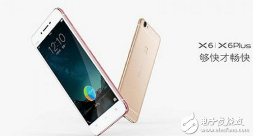
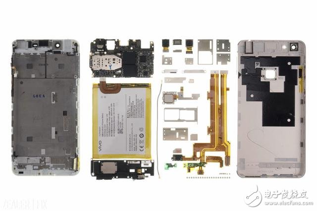
Today's manufacturers are on the road to pursuing differentiation, both from the inside out, from the outside and inside, all specializing in the industry. As one of the new flagship series of vivo, X6, can it make us feel refreshed? In the first time after getting the prototype, please also take a look at the engineers of ZEALER to see how much energy is hidden under this small body. (vivo X5 Max dismantling secret)
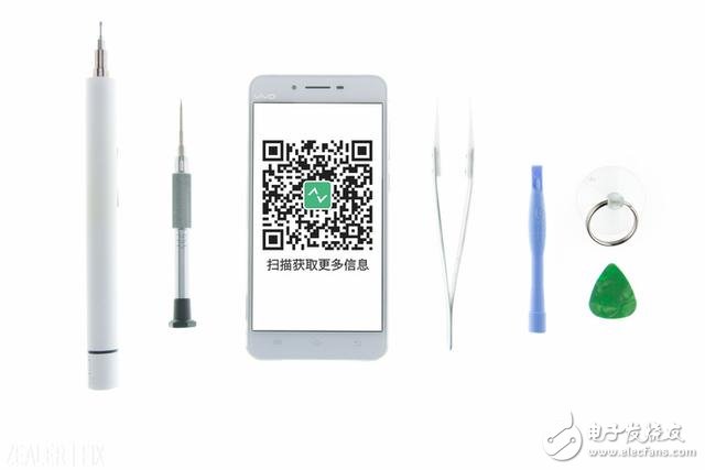
â–²The tools used in this disassembly include "Cross Phillips Screwdriver", "T6 Screwdriver", "Scorpion", "Crowbar", "Block", "Sucker" and "Hot Air Gun".
Step 1: Take out the "SIM card tray"
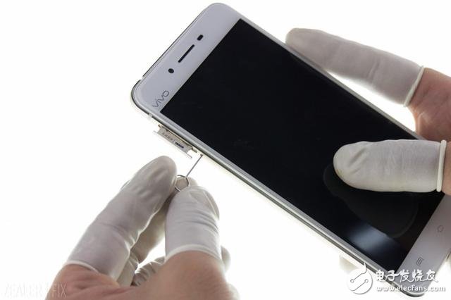
â–² Take out the "SIM card holder" located on the left side of the camera.
The slot of the vivo X6 is located on the body, and there is a spring of "SIM card" inside the body.
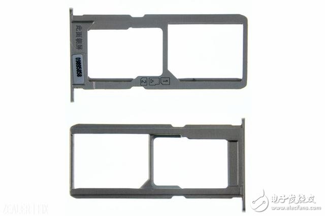
The one-piece aluminum alloy card holder does not have the structural design of the aluminum alloy cap and powder metallurgy tray.
Step 2: Remove the back cover
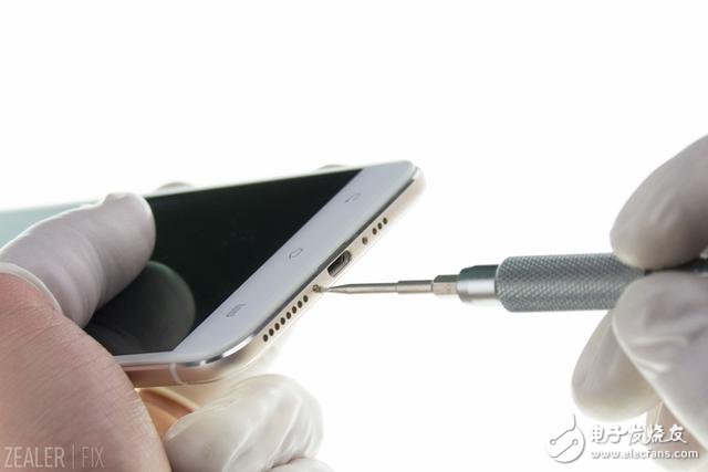
â–² Unscrew the 2 T6 screws at the bottom.
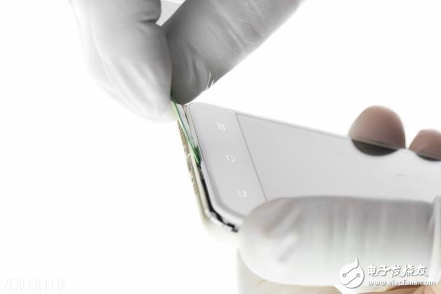
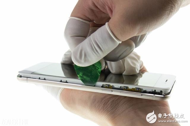
â–² After careful study by our ZEALER | FIX engineers, finally open a gap from the side of the Micro USB interface with a suction cup and a cymbal, then use a cymbal with a crowbar to open the back cover around; note that during the disassembly process Do not damage the "side button FPC".
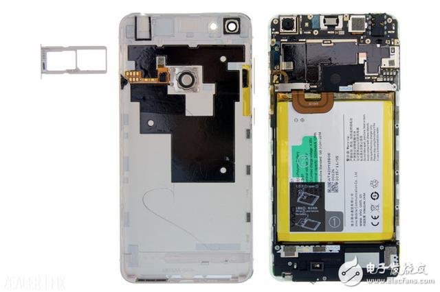
Here, the engineers of ZEALER | FIX repeatedly stressed that although the back cover of the vivo X6 is fixed by screws and buckles, the difficulty of disassembling itself is quite large. If it is necessary to repair and sell, it is recommended that users use official services. (OPPO R7 Plus comprehensive evaluation to achieve "big" has connotation).
Step 3: Power off the motherboard
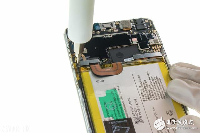
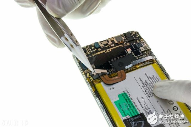
â–² Remove the screws at the fixed steel sheet and remove the fixed steel sheet.
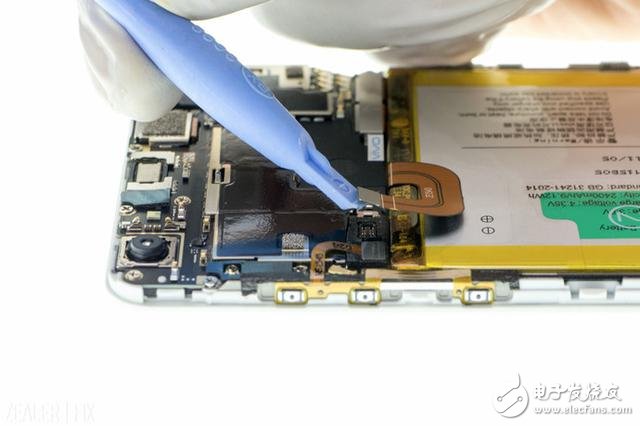
â–² Disconnect the battery BTB (Board to Board).
Step 4: Remove the motherboard
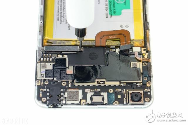
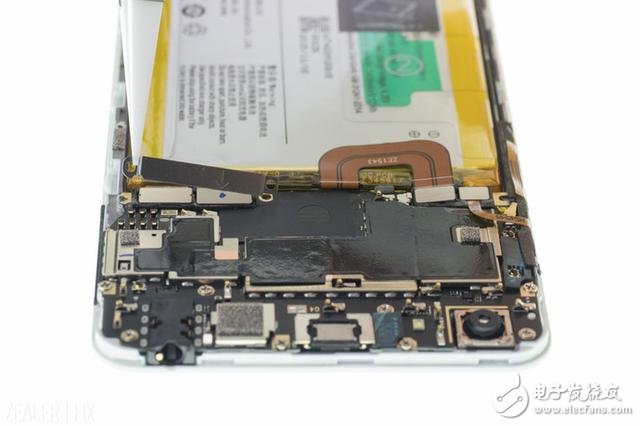
â–² Remove the 2 screws at the fixed steel plate and remove the fixed steel piece.
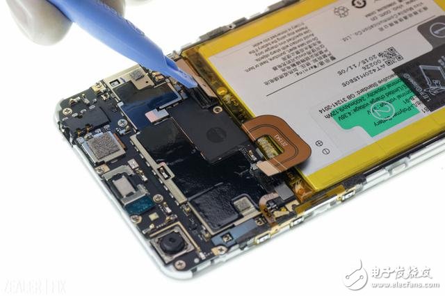
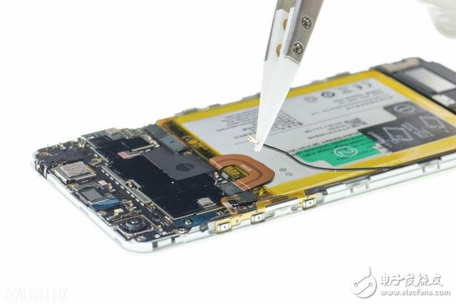
▲ Disconnect the BTB and the “RF connector†(RF antenna connector) on the motherboard.
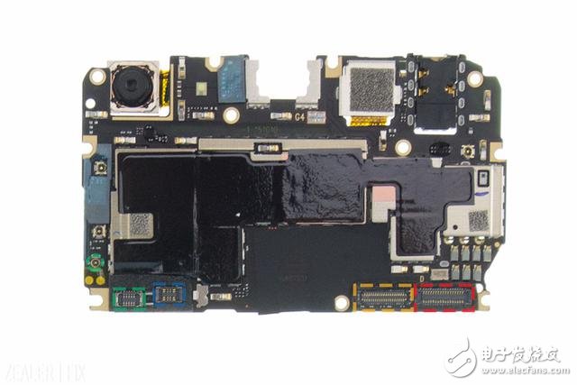
Green box: "Side button FPC" BTB
Blue box: battery BTB
Yellow box: "Main FPC" BTB
Red square: "Screen & Touch" BTB
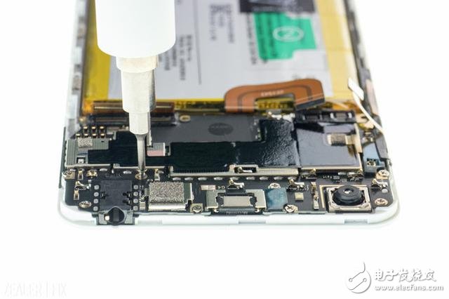
â–² Remove the screws that secure the motherboard.
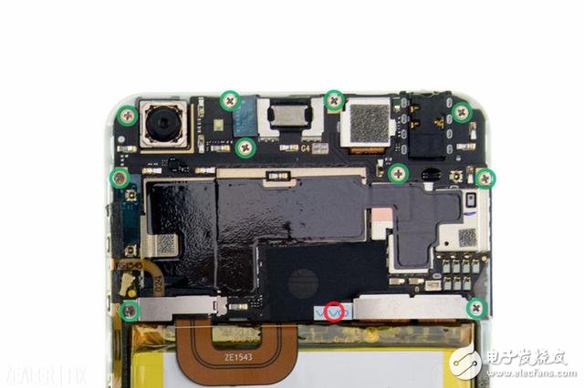
The vivo X6 shares 11 silver screws of the same size on the motherboard. Note that one screw is under the fragile label.
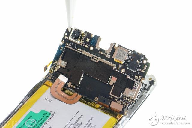
▲Slightly heat the “Back CAM†(rear camera) from the side of the screen and remove the motherboard.
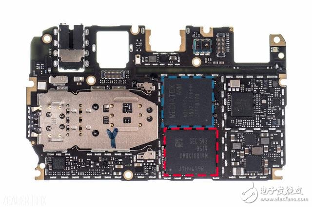
Blue box SOC: MTK MT6752v
Red block RAM & ROM: Samsung 4GB RAM & 32 GB ROM
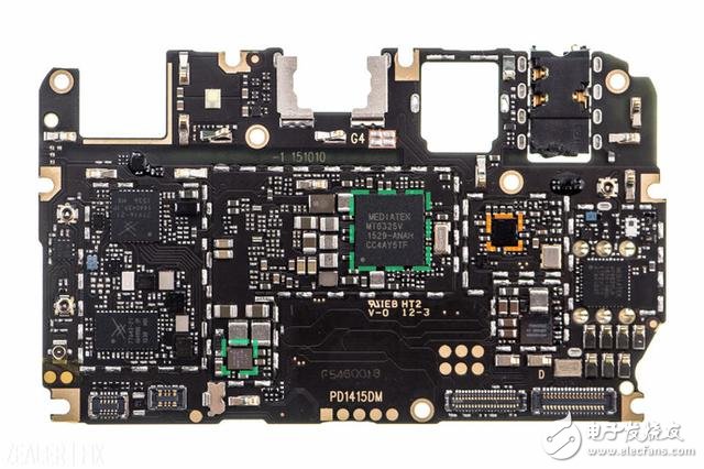
Green box POWER: MT6325V & MT6311P
Yellow box HiFi: AK4375A
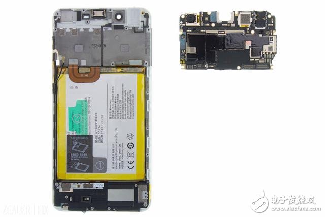
Step 5: Disassemble the handset, "front CAM", "post CAM"
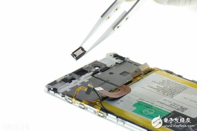
â–² Remove the handset.

The earpiece is not fixed with double-sided tape, and the foam rubber is placed on the screen holder and can be restored after being removed.
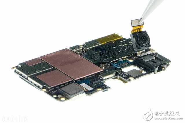
â–²Put up the "pre-CAM" BTB and remove the "pre-CAM".
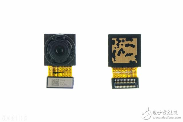
"Pre-CAM": 800W pixels
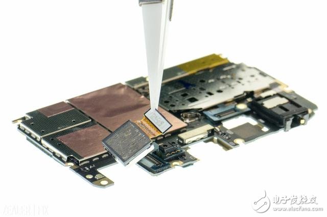
â–²Put up the "post-CAM" BTB and remove the "post-CAM".
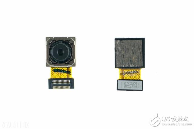
"Back CAM": 1300W pixels
The back of the "post CAM" has a conductive tape on the side of the screen assembly, so it needs to be heated slightly before removing the motherboard.
Step 6: Remove the battery
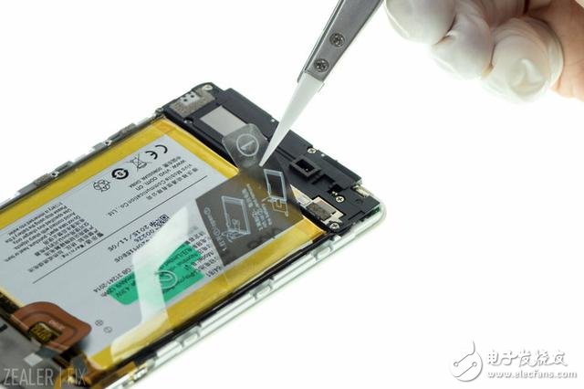
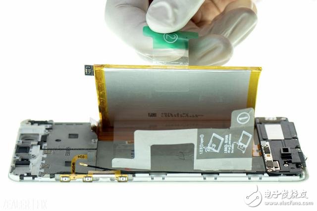
â–²After lifting the first transparent film, grab the tape at the handle and lift it up to remove the battery.
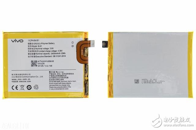
The battery capacity is 2400mAh and the output specifications of the power adapter are 5V/2A or 9V/2A.
Step 7: Disassemble "Trumpet BOX" and "Main FPC"
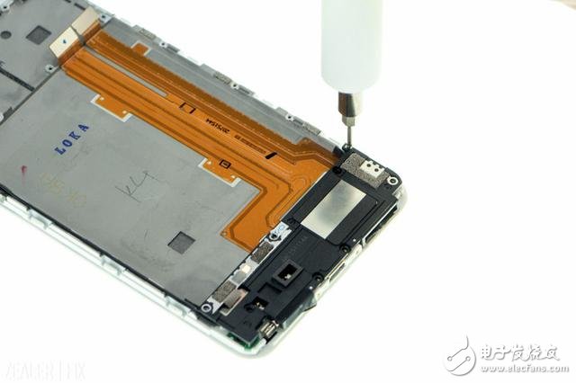
â–²After removing the screw on the “Blanet BOXâ€, it can be easily removed.
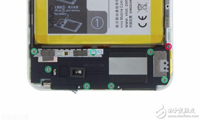
There are 1 + 7 screws here, the screws marked by the red circle are more slender than the rest, and the screws marked by the green circle are the same size as the motherboard.
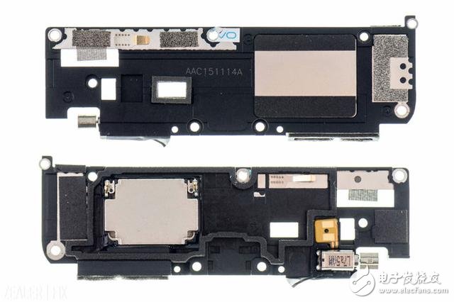
The vibration motor is fixed to the "horn".
Step 8: Disassemble "Main FPC", "Screen & Touch FPC"
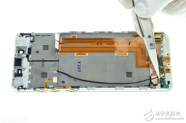
â–² Remove the coaxial cable.
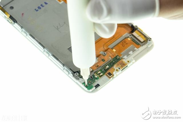
â–² Remove the screws at the antenna plate.
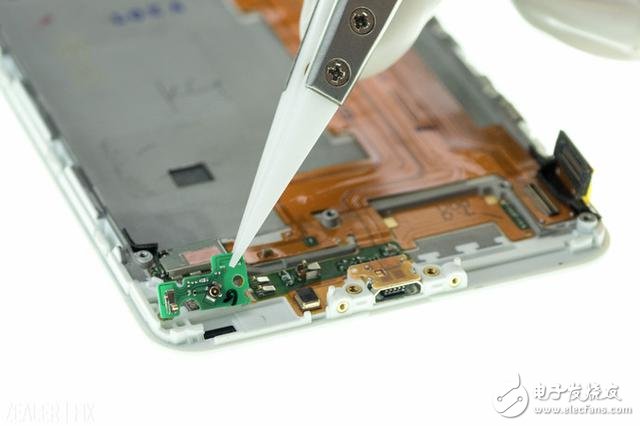
â–² Remove the antenna board.
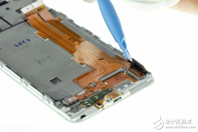
â–² Disconnect the BTB of "Screen & Touch FPC".
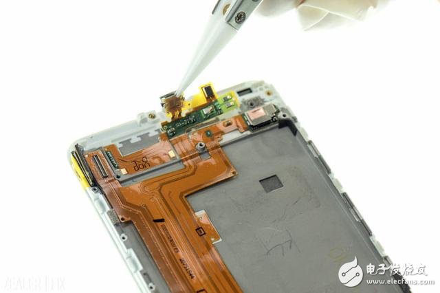
▲After heating the “Screen & Touch†BTB from the side of the screen, pick up the Micro USB connector.
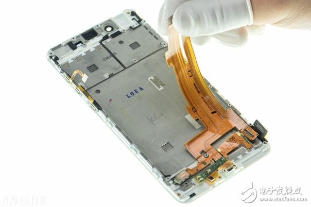
â–²Remove "Main FPC", "Screen & Touch FPC".
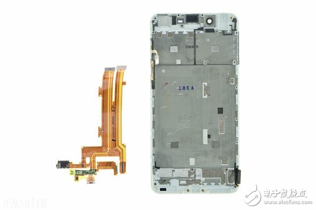
Step 9: Disassemble the "Fingerprint Identification Module"
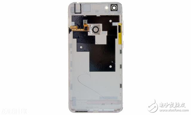
The metal back cover of the vivo X6 uses a nano-injection process with a plastic snap on the inside, but the middle frame of the rear case is made of metal, which makes it difficult to disassemble.
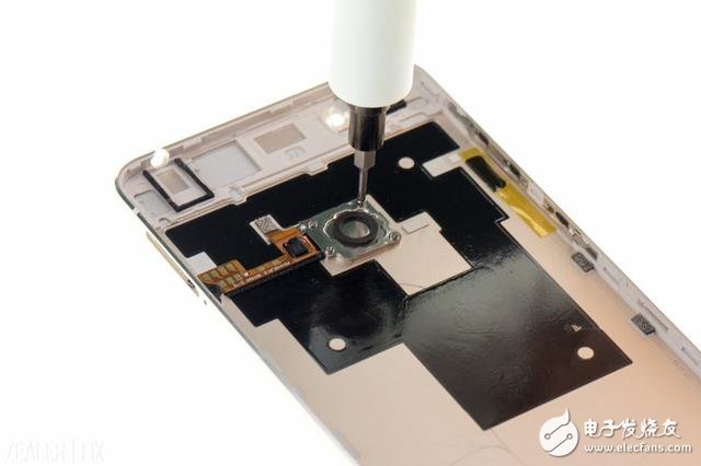
â–² Remove the 4 screws at the “Fingerprint Identification Moduleâ€.
The 4 screws here are smaller and different from the rest.
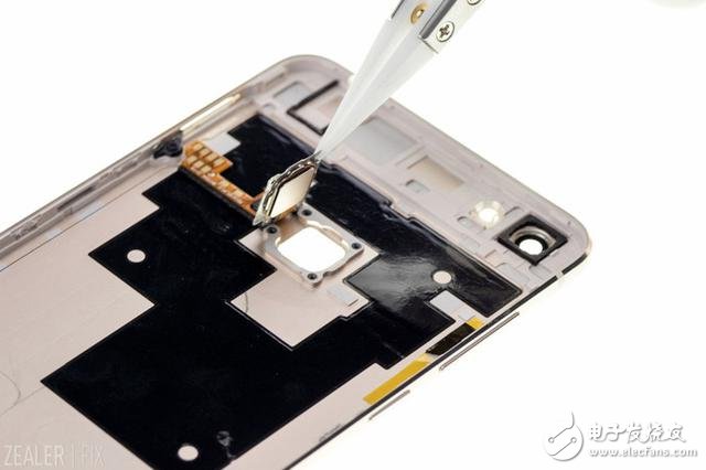
▲ Remove the “Fingerprint Identification Module†after heating from the back cover.
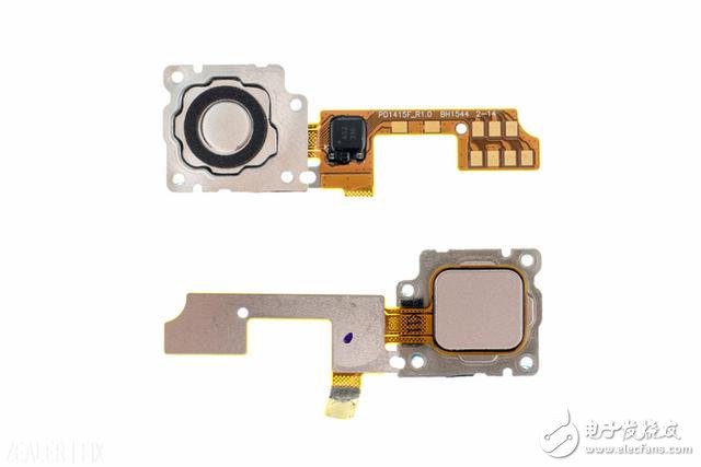
Unlike the "Fingerprint Identification Module" of Red Rice Note 3, which is fixed by foam rubber, the vivo X6 is fixed with a screw-locked steel sheet, and there is a circle of foam on the side of the fixed steel sheet facing the main board.
Jiangxi Huayang New Energy Co.,Ltd , https://www.huayangenergy.com