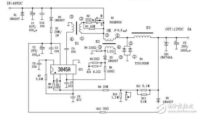
This figure is based on physical analysis. The power supply provides a voltage of about +12V for IC1 through D2 and R1. The output pulse of 6 pin drives Q1 oscillation after coupling with C4 and transformer. When Q1 is turned on, the output current passes through L filter after C9. Power is supplied to the load. When Q1 is cut off, the magnetic energy of the transformer-type inductor B3 is converted into electric energy, the polarity of which is left-right and right-right, and the free-wheeling diode D4 is turned on. The current continues to supply power to the load through the diode, so that the load obtains a smooth DC when the output When the voltage is too low or too high, the sampling voltage is obtained from the voltage dividing circuit composed of the resistors R11, R10, and R9, and is sent to the IC12 pin to compare with the internal 2.5V reference voltage to control the Q1 conduction pulse width, thereby stabilizing the output voltage. When the load current is short-circuited or exceeds 8A, the rise of IC13 pin voltage will control the pulse width to make Q1 cut off to ensure the safety of Q1. C8 and R7 constitute the oscillation time constant. The oscillation frequency of this circuit is 65KHz. The calculation formula is as follows:

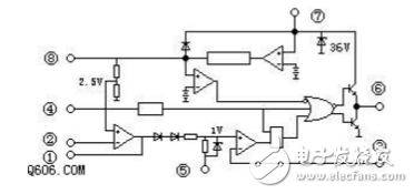
3845 internal structure and pin function

1 error amplifier output / compensation 2 voltage feedback input 3 current sampling input 4 oscillator circuit time constant 5 ground 6 switch tube drive pulse output 7 power supply 85V reference voltage is generally connected to the oscillator.

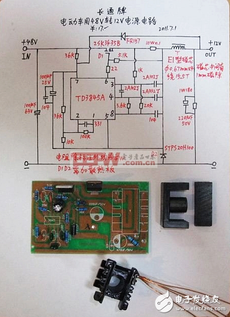
The electric vehicle uses 48V to 12V power supply circuit diagram, the input voltage range is 36V to 48V. The maximum current can reach 10a.

RAM/RFM electric heating capacitors
RAM/RFM Electric Heating Capacitors
Electric Heating Capacitor,Film Heating Capacitor,Electric Capacitor Bank,Induction Heating Capacitors
YANGZHOU POSITIONING TECH CO., LTD. , https://www.cnpositioning.com