Just a few years ago, "digital power" was just a concept, only a few prototypes for long-term evaluation, but few practical applications. By 2016, we have seen that digital power has become a standard for high-energy scenarios such as data centers. If there is no digital power, given the available space, efficiency requirements and thermal constraints, and other complex needs of these facilities, It is very difficult to provide hundreds of amps of power in different DC circuits.
Digital power is widely available in high-energy applications for several reasons:1. High efficiency can be achieved at lower operating costs; low heat consumption; easier to meet environmental regulatory requirements.
2. They can meet the challenging and complex technical requirements of processors and FPGAs.
3. During operation, it is highly flexible to handle complex power-up and power-saving sequencing scenarios.
Often, power supply designers (and many users) are very cautious, they are necessary to handle high currents, voltages, and power, otherwise the consequences are equipment failure and personnel safety issues. Prudent users tend to have long-term use records and use products that last for more than a decade, twenty years, or even longer. They don't want to order just because of the “technical frontiersâ€.
For these and other reasons, some people in the early days were reluctant to accept a firmware-based approach, but this has changed. Since the tracking records of high-end digital power supplies are backed by reliable data, other application areas such as industrial systems can also benefit at a lower level. Benefits include improved power from low load to full load, which saves energy, reduces component thermal stress, simplifies cooling and increases MTBF (mean time between failures).
Popular science concept of "digital power"In fact, the goal of a power supply or converter is simple: to provide a stable, controlled DC output at a desired voltage value in the event of a change in input voltage or load conditions. This requires some form of closed-loop control in the DC/DC converter, based on the actual output voltage measurement, compared to the setpoint, and feedback-based correction to force the output back to the setpoint and save.
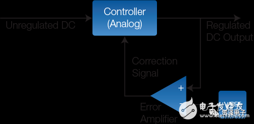
This regulaTIon has tradiTIonally been implemented using a closed-loop negaTIve-feedback with analog circuitry in a switching regulator, Figure 1. (The alternaTIve, a low-dropout regulator, or LDO, is also an option, but only viable at fairly low power Levels.) there are many standard architectures for these switchers, with a long list of additional enhancements to increase efficiency across the entire load range, boost performance and ensure consistent operation. These enhancements can become quite complicated and clever, and have impressive names such as SEPIC (single-ended primary-inductor converter).
This rule has traditionally been achieved by using closed-loop negative feedback and using analog circuitry in the switching regulator, see Figure 1 (low-dropout regulator LDO is also an option, but only when low power is available). These converters come in many standard architectures with a range of additional enhancements that increase efficiency, performance and consistency across the entire load range. These enhancements are complex and flexible, with an impressive name such as SEPIC (Single-Ended Main Inductor Converter).

Figure 1: The standard analog power converter uses a well-known closed-loop topology that maintains the specified DC output even if the input and load change.
These variables can be quite complex, but they all have one drawback: the lack of flexibility in real-time settings of operational parameters. For example, the Intel/XilinxVR13 standard requires that the rated output voltage be changed directly from 1.2V to 0.9V, and then back to "flying write", which is completely impossible to complete with analog power. This adaptive voltage scaling (AVS) adjusts the supply output voltage to meet the processor's minimum requirements based on the processor's clock speed and workload, while automatically compensating for process and temperature variations within the processor. To do this, you need a fully programmable, complex, firmware-controlled converter.
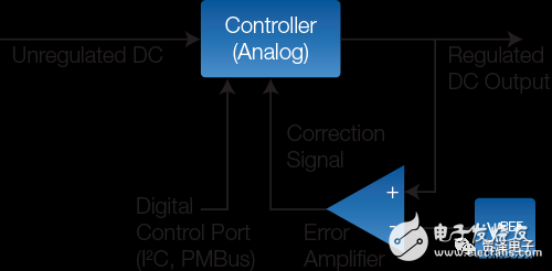
Some of the required changes can be made through an I/O port and digital parameter setting circuitry. This results in a hybrid power supply with an internal analog control loop, but with overall digital monitoring and some supply status reports, see Figure 2.

Figure 2: The enhanced analog controller retains the basic closed-loop design, but allows digital settings of the parameters under external control via digital ports (such as PMBus, I2C, SPI, etc.).
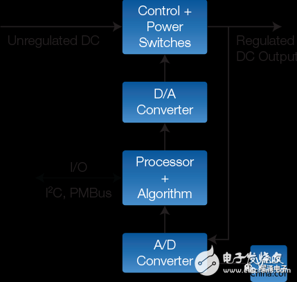
All digital power supplies use a completely different internal architecture. Digital power uses an analog/digital (A / D) converter to digitize critical internal voltages and currents instead of using analog circuitry or even digital supervision to implement the control loop. The converted value is used by a dedicated embedded processor (DSP, FPGA) that executes the code of the closed loop algorithm. Finally, through a digital/analog (D / A) converter, the results of the algorithm are converted back to analog and the voltage and current are adjusted as needed, as shown in Figure 3.

Figure 3: The all-digital control method instantly digitizes critical voltages and currents and then uses firmware-driven processors and algorithms to initiate control actions, enabling complex control strategies and dynamic adjustments as needed for the environment.
The control algorithm is based on firmware, not hardware analog circuitry, so the control strategy is quite complex. A better improvement is that a single processor (if strong enough) can control two or more independent output lines and coordinate these lines to manage factors such as output level, slope, and relative power between lines. It also provides detailed reports and historical data about supply status, conditions, and change information, so failures can be foreseen, not reported after they occur.
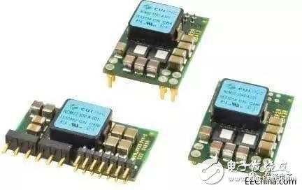
Here are two examples of how digital devices can serve applications with lower current and power requirements than data centers. The NDM2Z-50 from CUI (Figure 4) is an all-digital DC/DC point-of-load (PoL) converter with an input range of 4.5V to 14V, programmable output of 0.6V to 3.3V, and current up to 50A ( The maximum value is 165 W). It includes an SMBus interface and is compatible with PMBusTM. Despite having a small package (30.85 x 20.0 x 8.2mm lateral mount), it also provides such things as voltage tracking, voltage edge, active current sharing, parameter capture, voltage/current/temperature monitoring, and programmable soft start and Features such as soft stop. Its data sheet (Reference 1) includes a variety of charts showing static and dynamic performance.

Figure 4: The CUI all-digital DC/DC PoL converter will provide up to 50A of data, and it is also part of a more efficient or lower, flexible, compatible and feature-rich DC/DC converter that can Meet the needs of larger applications. (Source: CUI Inc.)
to sum upAt present, the power supply requirements of many electronic systems are increasing. Even advanced analog power supplies cannot meet the demand, but a new power supply architecture is needed for control. All digital power supplies will have significant and tangible benefits due to their flexibility, performance and adaptability. Although conceptually and operationally distinct from traditional analog-based power supplies, digital power designs are increasingly mature and are rapidly expanding to other applications.
Flat Key (No embossed) Membrane Switch
Working Voltage
≤50VDC
Working Current
≤100mA
Contact Resistance
0.5~10Ω
Insulation Resistance
≥100MΩ
The Base Pressure
2kDVC
Recoil Time
≤6ms
loop resistance
50Ω,150Ω,350Ω or custom
Insulating ink withstands pressure
100VDC
Reliability life
>1000k times
Closing displacement
0.1~0.4mm (no touch) 0.4~1.0mm
Health standard for force
15 ~ 750 g
Migration of silver paste
In 55 ℃, the temperature is 90%, 56 hours later,
the second line is between 10 m Ω / 50 VDC
Silver pulp line
No oxidation, no impurities
Silver pulp line width
≥0.3mm
Line burrs
<1/3
circuit nick
< 1/4 line width
Standard pin spacing
2.54 2.50 1.27 1.25mm
Lead resistance to curvature
With d=10mm steel, the bar is pressed 80 times continuously
operating temperature
-20℃~+70℃
Storage Temperature
-40℃ ~ +85℃ temperature 95%±5%
barometric pressure
86~106KPa
Print size deviation
±0.10mm,The edge line of the appearance is unclear and the difference is ±0.1mm is unclear and the difference is ±0.1mm
Color deviation
±0.11mm/100mm
The insulating ink is fully covered with the slurry line
No ink loose, no incomplete writing
Chromatic aberration is not greater than two lever
No creases, no paint removal
Transparent window
Clean, uniform color, no scratch,pinhole, impurities
China Membrane Switch, Membrane Switch Manufacturer, Membrane Switch, Flat Key Membrane Switch, Membrane Keypad, Membrane Keyboard
KEDA MEMBRANE TECHNOLOGY CO., LTD , https://www.kedamembrane.com