A lightning protection design technique is introduced that converts the transient signals experienced by components during an instantaneous lightning strike test into reference transient signals as indicated on the component's data sheet. This makes it easy to select components that are suitable for the application and avoid trial and error in the design process.
In addition, a technique for determining the minimum wire width required to withstand transient signals is also described. This article introduces a free graphical user interface (GUI) that can be used to complete all the calculations mentioned in reference [1] and output the results. Then we can compare these results with the data sheet, select the appropriate components, and finally design a very robust lightning protection circuit.
In order to create a lighter aircraft to consume less fuel, aircraft manufacturers have begun to use carbon composite materials instead of aluminum to make the fuselage. The side effect of this change is to increase the degree of indirect impact of lightning strikes on the fuselage on the electronic equipment (avionics) used on the aircraft. More severe transient lightning strike signals require a more robust transient protection for the avionics interface. More powerful protection features often require larger components. But aircraft manufacturers and avionics suppliers want to keep the size of existing equipment constant. Therefore, additional lightning protection circuits must be carefully designed to enable the use of components of the smallest physical size.
The data sheet for the components used in the lightning protection circuit provides a rating based on the reference transient signal. These transient signals are different from the lightning transient signals encountered by circuits exposed to the aircraft environment. The typical design approach is therefore to select components by experience. Another technique is to use the largest component that can be mounted on a printed circuit board (PCB). The width of the wires used in the circuit used to depend on the general IPC (formerly known as the Printed Circuit Board Association, now referred to as IPC) guidelines.
However, these guidelines were developed for continuous currents, so the wire width is much wider than the requirement to withstand transient currents. After preliminary design, prototypes need to be built and tested. The test results are then analyzed to determine if the device and wire widths used in the circuit are appropriate. This “trial and error†process delays progress and increases the use of resources. These delays can be prevented using the graphical user interface (GUI) discussed in this article.
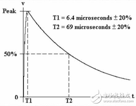
Chapter 22 of Ref. [2] contains lightning impulse test transient signals required by the Federal Aviation Administration (FAA) for indirect lightning strike testing. Waveform 4 (WF4) shown in Figure 1 is an instantaneous test signal for a metal aircraft.

Figure 1: Waveforms mentioned in Chapter 22 of Reference [2].
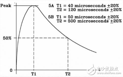
Waveform 5A (WF5A) shown in Figure 2 is for a synthetic material aircraft. The parameters related to this waveform are open circuit voltage (VOC) and short circuit current (ISC). These values ​​can be used to calibrate the source impedance of the transient signal generator used for the test.

Figure 2: WF5A mentioned in Chapter 22 of Reference [2].
In order to determine the test level of the avionics, the instantaneous lightning strike signal must be applied to the fuselage or simulated. Reference [3] describes transient signals applied to the fuselage or simulated at different locations (zones) determined by the literature [4]. This test or simulation will produce voltage values ​​associated with each zone. For avionics connected to each other, it is necessary to calculate the sum of the voltages of the various zones through which the connecting cable passes, and then double the test value for each signal line.
Applying to the fuselage using the process in [3] to determine the instantaneous lightning strike current of the avionics test level has the same rise time and pulse width as WF4. Synthetic material fuseries can severely distort this transient signal, and the distortion produced by the metal body is negligible. Therefore, the WF5A is longer in duration than the WF4. In addition, the composite fuselage will transfer more energy from the instantaneous lightning strike signal to the avionics. To simulate this phenomenon during the test, the WF5A also has a source impedance of 1 Ω, while the source impedance of the WF4 is 5 Ω.
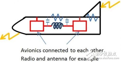
The distortion produced by the fuselage is caused by the diffusion of the composite material body and the structural voltage drop (current x resistance) coupling. Figure 3 is a simplified visual depiction of these couplings.
Avionics are connected to each other, such as radios and antennas.

Figure 3: Indirect impact of lightning strikes on avionics. In this example, the lightning strike signal is accessed from the tail and escapes from the nose. The test level determination process in [3] changes the access escape point across the entire fuselage. The blue component is a simplified model of the coupling of diffusion and structured pressure drop. This model is a modified version of the model in [5].
When describing the structural pressure drop and diffusion coupling, the fuselage can be thought of as a resistor through which a lightning current flows. The avionics connected to each other through signal lines are in parallel with this resistor. Cables that connect avionics can be represented by inductors and capacitors. The current flowing through the resistor represents a structured voltage drop coupling, while the reactance component represents a diffusion coupling. The combination of the two couplings will further lengthen the waveform. Since the WF5A has a longer duration and a lower source impedance, more energy is transferred to the avionics at the same level.
Conecting Terminals Without Screws
Conecting Terminals Without Screws,Cold Pressing Terminals,Low Pressure Cold Shrinkage Terminal,Cold Shrinkage Cable Terminals
Taixing Longyi Terminals Co.,Ltd. , https://www.longyiterminals.com