There are too many materials for introducing TVS tubes, and there are many Chinese ones, but most of them are translated. At the end of the article, there are directories and downloads of all the files. Here mainly introduces the principle characteristics and parameters, and then draw some time to analyze the heat selection, and finally summarize the PCB. The transient diode [TVS|Transient Voltage Suppressor] is a high-performance protection device in the form of a diode (the evolution of Zener diodes). When the two poles of the TVS diode are subjected to reverse transient high energy impact, it can change the high impedance between the two poles to a low impedance at an extremely fast speed, absorbing the surge power between the power supply and the signal line, so that the two poles The voltage clamp is at a predetermined value.
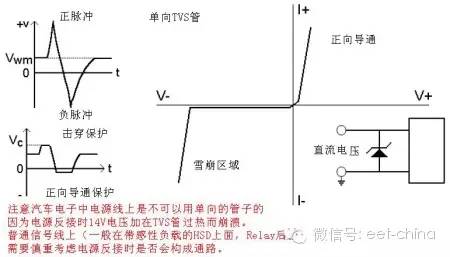
Bidirectional TVS and unidirectional TVS unidirectional TVS are similar in nature to Zener tubes and can only absorb forward surge voltage pulses, typically only for DC circuits (and without reverse and negative pulses).
The two-way TVS can absorb the surge voltage pulse in both positive and negative directions, and the voltage clamping is realized. The two-way TVS is widely used (DC and AC are available).
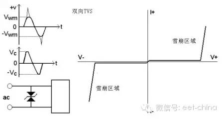
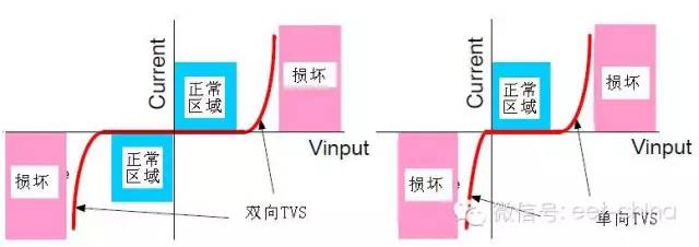
See the comparison below for a clearer picture:
TVS tube features:
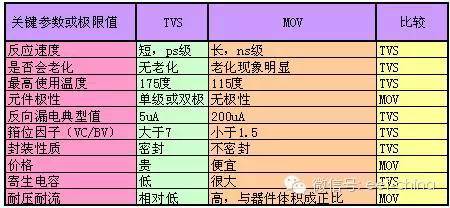
Advantages: fast response time, high transient power, low leakage current, easy control of clamping voltage, no damage limit, small size and so on. Disadvantages: The breakdown voltage is lower and the price is more expensive. Comparison with MOV:
TVS tube parameters:
1) Breakdown voltage [V(BR)] In the region where breakdown occurs, TVS measures the voltage across the device under the specified test current I(BR) as the breakdown voltage. 2) Maximum reverse pulse peak current [I.PP] The maximum pulse peak current allowed by the device during breakdown [under specified pulse conditions].
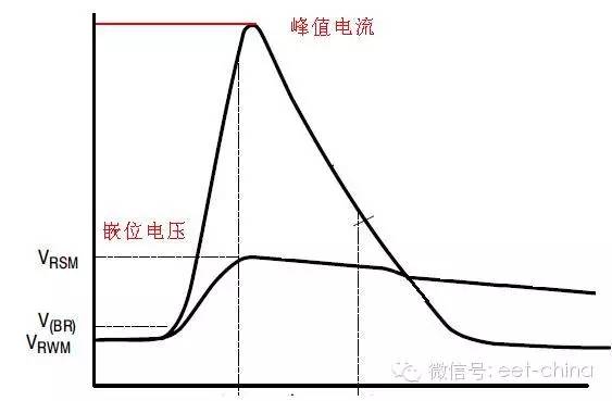
We should pay attention to this parameter because the maximum value of transient pulse power = IPP × maximum clamp voltage VC (MAX). To ensure that the TVS is working properly, it is necessary to confirm that the rated transient pulse power PPR is greater than the maximum transient surge power.
In fact, the test waveform of the peak current uses a standard wave (exponential waveform), which is determined by TR/TP. Peak current rise time TR: The time from 0.1 IPP to 0.9 IPP. Half-peak current time TP: The time that the current drops from zero to 0.5IPP after passing the maximum peak.

3) Maximum reverse working voltage [VRWM]
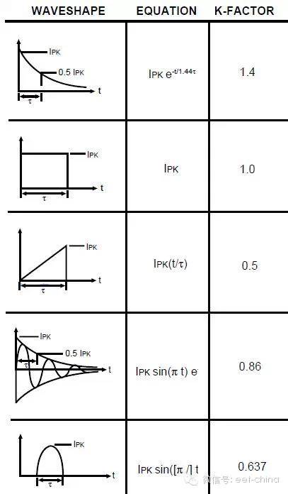
During the TVS protection circuit, the voltage value across the TVS is called the maximum reverse operating voltage VRWM under the specified reverse current. Generally VRWM = (0.8 ~ 0.9) V (BR). At this voltage, the power consumption of the device is small. We generally choose devices with VRWM greater than 16V. 4) Maximum clamp voltage [VC(max)] The maximum voltage across the device under the pulse peak current Ipp is called the maximum clamp voltage. When using, make VC(max) no higher than the maximum allowable safety voltage of the protected device. The ratio of the maximum clamp voltage to the breakdown voltage is called the clamp factor. 5, reverse pulse peak power PPR TVS PPR depends on the pulse peak current IPP and the maximum clamp voltage VC (max), in addition to the pulse waveform, pulse time and ambient temperature. When the pulse time Tp is constant, PPR = K1 × K2 × VC(max) × Ipp, where K1 is the power coefficient and K2 is the temperature coefficient of the power. A typical pulse duration Tp is 1 MS. When the pulse time tp applied to the transient voltage suppression diode is shorter than the standard pulse time, the pulse peak power will increase as tp is shortened.
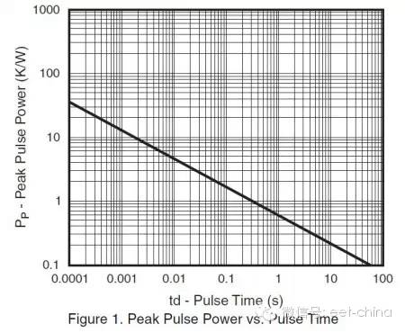
The reverse pulse peak power PPR of TVS is related to the pulse waveform subjected to surge, and is expressed by the power coefficient K1: E=∫i(t)?V(t)dt, where: i(t) is the pulse current waveform, V (t) is the clamp voltage waveform.
This rated energy value is not reproducible for TVS in a very short time. However, in practical applications, surges usually occur repeatedly, in which case even if the individual pulse energy is much smaller than the pulse energy that the TVS device can withstand, if repeated application, these individual pulse energies It accumulates and, in some cases, exceeds the pulse energy that TVS devices can withstand. Therefore, the circuit design must carefully consider and select the TVS device at this point so that the accumulated pulse energy accumulation does not exceed the pulse energy rating of the TVS device at the specified interval.
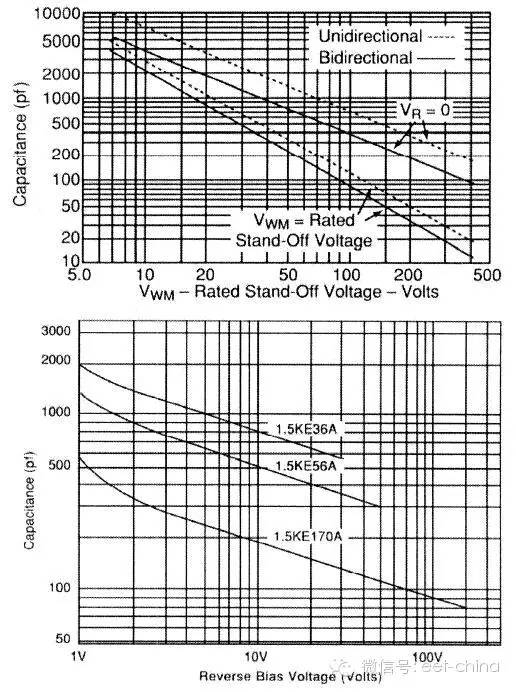
6. The capacitance of the capacitor CPP TVS is determined by the area of ​​the silicon chip and the bias voltage. When the capacitor is in the biased case, the capacitance value decreases with the increase of the bias voltage. The size of the capacitor affects the response time of the TVS device.
7, leakage current IR
When the maximum reverse operating voltage is applied to the TVS, the TVS tube has a leakage current Ir, which affects the quiescent current in automotive electronics.
PUR Cable,Highly Resistant Against Wear Cable,Shielded Polyurethane Cable,Oil Resistant Cable
Ruitian Cable CO.,LTD. , https://www.hbruitiancable.com