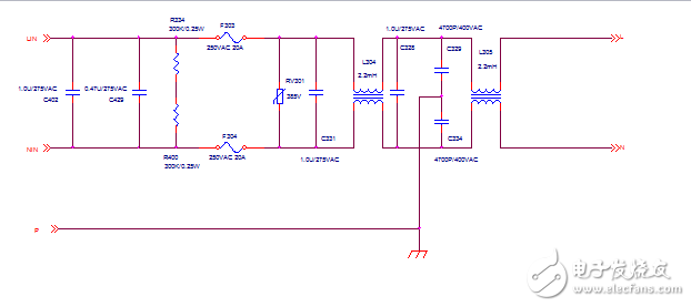
Abstract: This paper introduces a single-phase input EMI power filter circuit, which is generally used as an input part of a small and medium power supply to meet the EMC requirements of the power supply.
Abbreviated explanation
EMC: ElectromagneTIc CompaTIbility, electromagnetic compatibility
EMI: ElectromagneTIc Interference, electromagnetic interference
1. Scope of application
The unit circuit parameters can be used for most small and medium power supplies as long as they are properly debugged and modified.
2. Satisfied technical indicators (characteristic indicators)
The specifications of the power supply are:
Input: AC 120V~290V
Output: 48V/50A
Output power: 2900W
3. Detailed circuit diagram

Figure 1 Unit circuit schematic
4. Introduction to working principle
The line filter is a low pass filter network of passive components. It transmits 50 Hz, 400 Hz AC power to the device without attenuation, but greatly attenuates the EMI signal transmitted through the power line to protect the device from damage. At the same time, it can suppress the EMI signal generated by the device itself, prevent it from entering the power grid, pollute the electromagnetic environment, and harm other devices. The power EMI filter is an effective device for electronic devices to meet electromagnetic compatibility standards.
The core components that make up the power EMI filter are: common mode inductor, differential mode inductor, X and Y capacitors. The common mode inductor and the Y capacitor together form an LC two-stage low-pass filter, which is mainly used to suppress common mode noise. In addition to minimizing stray capacitance during winding, the unbalanced inductor should be properly controlled (generally about 1%). 〕 Although the unbalanced inductor has the effect of suppressing the differential mode noise, the unbalanced inductance is too large, which tends to cause the core-saturation of the common-mode inductor. The suppression and filtering of the differential-mode noise is caused by the differential-mode inductor and the X-capacitor. To be completed, the EMI filter is mainly to solve the EMI problem from the aspect of noise propagation. All EMI circuits can only reduce the impact of electromagnetic interference on the performance of the whole machine to a certain degree. It should also be combined with the work of the noise source, such as reducing the peak of the switching amount, using reasonable absorption or soft switching technology to reduce the emission value of the power supply noise, this article will not discuss in detail.
5. Design and debugging points
1. First test the conducted interference when the EMI filter is not installed, and compare with the standard limit, list the insertion loss of the EMI filter in each frequency band (within 150K~30MHz).
The LSN and N-line conducted interference test outputs of LISN have differential mode noise and common mode noise components, respectively.  ,
,  If the addition and subtraction are applied to them, the common mode interference can be directly obtained.
  And differential mode interference
  . To achieve the above objectives, a 0° power combiner and a 180° power combiner are used, respectively.
2. Determine the number, structure, component parameters, etc. of the EMI filter based on the difference between the conducted interference and the standard limits tested without the EMI filter, and the existing space and cost requirements of our products. To meet the insertion loss requirements of EMI filters in different frequency bands.
[1] According to the rigor of the product's requirements for electromagnetic compatibility, combined with the existing test results of interference without EMI filter, determine the number of stages:
Generally, the requirements of the Class B standard are as follows. The number of stages of the filter generally requires two or more stages. If the stray inductance of the common mode inductor is properly utilized, only two common mode inductors can be selected to match the corresponding Y and X capacitors. To achieve, if there are no other reasons or conditions, you can consider the choice of two-stage common mode and first-order differential mode inductors with the corresponding X and Y capacitors, design and commissioning is relatively simple.
Because the new 50A module requires small size and high power density, the volume left for the input EMI filter is very limited, so the project team invested a lot of manpower and material resources to conduct EMC research and development. Class B requirements are achieved using a two-level common mode.
〖2〗 Determine the structure of the power supply filter according to the parameters of the circuit:
The structure of the power supply filter is a decisive factor for the effect of the filter to a large extent. In order to achieve the best suppression effect, we require the impedance of all the ports of the filter and the equivalent input of the corresponding device or functional circuit. The impedance is heavily mismatched. The following connections are considered to be the correct connections in the design of the EMI filter:
Taxi Rear Window Led Screen,Rear Window Led Display,Led Screen Car Advertising,Vehicle Mounted Digital Signage
ShenZhen Megagem Tech Co.,Ltd , https://www.megleddisplay.com