0 Preface
This article refers to the address: http://
In the single-chip application system, the serial data communication usually adopts the chip 8251. However, because the communication baud rate of the 8251 is not high, it cannot be applied to a system with a high crystal oscillator, which makes the system requiring high running speed and high-speed data transmission and reception cannot be applied. The 8251 chip sends and receives data, and the 8251 requires an 8253 to provide an external clock signal. MAXIM's new UART chip, the MAX3100
Just fill this gap. The MAX3100 supports high-speed communication with a maximum communication baud rate of 230KBPS, low power consumption, low voltage support, and a small system design, which is less than half the size of a printed version of the external clock 8253. And it can make software design more reliable.
The organic light-emitting display OLED is a new-generation flat panel display technology which is more advanced than the liquid crystal display technology, and is recognized as the most promising next-generation display technology in the industry. Compared with liquid crystal display technology, OLED (Organic Light Emitting Display) has ultra-thin, high brightness, wide viewing angle, self-illumination, fast response, wide temperature range, strong shock resistance, low power consumption, and soft display. Such superior performance, OLED screen is rapidly expanding its application share in the portable electronics market, and can be applied to harsh environments such as communications, mapping, railways and weapons.
1 main working principle
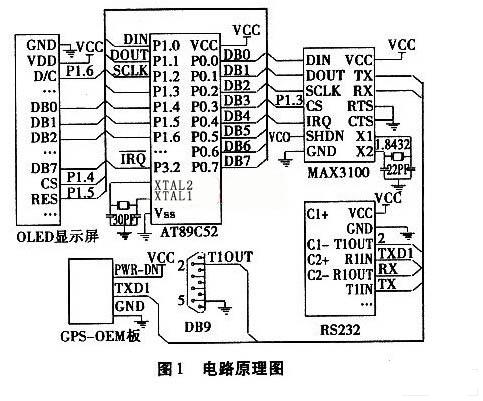
The system is mainly composed of AT89C52 single-chip microcomputer, MAX3100 universal asynchronous transceiver, GPS-OEM board, OLED display and so on. The AT89C52 MCU receives the NEMA statement from the GPS-OEM board through the MAX3100, and calculates the positioning information (including: latitude, longitude, altitude, speed, date, time, heading, satellite status, etc.) after software programming, and displays it on the OLED display. come out. And through the MAX3100, these positioning information is output as RS232 standard serial port data. The schematic diagram of the system circuit is shown in Figure 1.
2 Data communication between MCU and GPS-OEM board
The data communication between the MCU and the GPS-OEM board is realized by the MAX3100 universal asynchronous transceiver. The oscillation frequency of the MCU is 11.0592MHz. First, the MAX232 level conversion chip is used to achieve bidirectional conversion between RS232 level and TTL level, because the serial level of the GPS OEM board is in accordance with the RS232 standard level, and the MAX3100 uses the TTL level.
The DIN pin of the MAX3100 is the serial data input and DOUT is the serial data output. The rising edge of the serial clock latches the DIN data, and the DOUT data is synchronously output by the falling edge of the serial clock. The serial data sequence of the DIN and DOUT pins of the MAX3100 is 16-bit data, with the first two bits of the DIN data sequence characterizing the data type of the string. When the current two bits are "1, 1", it indicates the write command. When the current two bits are "0, 0", it indicates that the data is read. When the current two bits are "1, 0", it indicates that the data is written.
Initial configuration of the MAX3100 is done by the microcontroller by writing a sequence of commands. The command sequence includes parity bits, data bits, stop bits, baud rate settings, data word length, check FIFO, interrupt enable, and more. The MAX3100 has its own baud rate generator, which can be used with a crystal with a frequency of 1.843 2 MHZ or 3.6864 MHZ. The baud rate is determined by the last 4 bits B0 to B3 of the write command sequence.
When the MCU receives the serial port data of the GPS OEM board, it is completed by reading the MAX3100 data sequence. When the MCU reads data from the MAX3100, it needs to write a 16-bit word (0000H) in DIN and then read 16 bits from DOUT. The upper eight bits of the word are: the status of the receive/transmit buffer, the data error/overflow status, the receive/check bit status and the CTS status. The lower eight bits are the serial port data of the received GPS OEM board.
When the MCU sends the final positioning data, it is completed by writing a data sequence to the MAX3100. When the MCU writes data to the MAX3100, it writes a 16-bit word in DIN. The contents of the upper eight bits are: Write flags, enable TX output, RTS pin settings, and transmit parity settings. The lower eight bits are the data to be transmitted.
3 OLED display shows positioning information
The display module display has 128 columns and 64 rows, and has 1 row driver and 2 column drivers. The row driver has 64 rows of output, and each column driver has 64 outputs. The drive signal and the sync signal can be generated as long as the power supply is provided, and the external signal of the module is only related to the column driver. The column driver has built-in 64×64-bit display memory. The display status of each pixel on the display screen is in one-to-one correspondence with the data of the display memory. The data of the display memory is directly used as the driving signal for the graphic display. When it is “1â€, it is displayed as “Oâ€. "Do not show when." The OLED display in the system displays positioning information such as latitude, longitude, altitude, speed, date, time, heading, and satellite status.
4 software design
4.1 Application of watchdog interrupt
The 6-pin and 7-pin of the MAX706 are connected to the P1.7 of the AT89C52 and the reset pin. In the software program, a watchdog counter reset command is inserted every other program, so that if the program enters an infinite loop or In the illegal code area, the system will be reset to ensure the normal operation of the system.
4.2 Delay processing
When the data to be sent is sent to the transmit buffer, since the MAX3100 waits for T=1, the transmit buffer is empty, and it can receive another data to be sent. Therefore, it is necessary to add an appropriate delay at this time. , can guarantee that the data sent is accurate.
4.3 Creating a font
In the implementation of OLED display, the Chinese characters that need to be displayed are first composed into a Chinese character library, and the English characters or Arabic numerals form a Western character library.
For example, if the Chinese character is “effectâ€, set Song No. 12, the corresponding dot matrix is ​​width × height = 16×16, and the 32 bytes corresponding to the horizontal mode of the modulo software are: {O×10, 0×20, 0× 08,0×30, O×08, 0×20, 0×7F, O×20, 0×14, 0×7E, 0×12, 0×44, 0×21, 0×C4, O×22, 0×44, O×62, 0×28, O x 14, 0×28, O×08, 0×10, 0×0C, 0×10, O×12, 0×28, 0×20, 0× CE, 0×C3, 0×04, O×00, 0×00}.
The Arabic numeral "1", set Song No. 12, the corresponding dot matrix is ​​width × height = 8 × 16, and the 16 bytes corresponding to the horizontal mode of the modulo software are: {0×00, 0 x0o, 0×00, 0×10, 0×70, 0×10, 0×10, O×10, 0×10, 0×10, 0×10, O×10, 0×10, 0×7C, O×00, O× 00}.
4.4 Software Essentials Design
When designing the software, there are two key designs. One is to process the GPS module data received by the serial port; the other is to display the required positioning information on the OLED display. The software flow chart is shown in Figure 2.
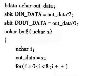
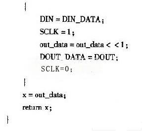
Define an 8-bit bit subroutine in the MAX3100. The C language code is as follows:
The task of this subroutine is to perform two tasks by performing 8 shift operations on the DIN and DOUT pins of the MAX3100. The first is the receiving part. After initializing the configuration, the RX receives the NEMA statement of the GPS module and sends it to the receiving. Buffer. Next is the transmitting part, which receives the SPI data and performs a transmission buffer, which is sent out asynchronously through the TX.
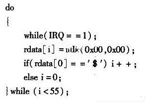
When receiving a NEMA statement, it starts with the beginning of the line "$". Before further processing, the NEMA statement is a long stream of bytes. This information cannot be utilized until it is sorted and extracted. Therefore, it must be processed by a software program. The information of each field is extracted from the byte stream and converted into positioning information such as latitude, longitude, altitude, speed, date, time, heading, and satellite status.
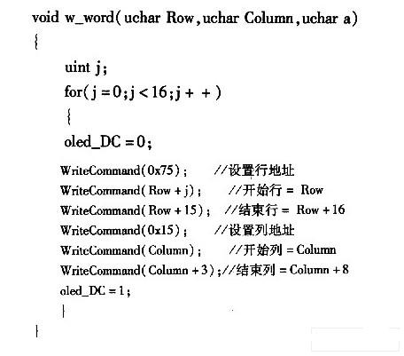
Displaying a certain positioning information at a certain position on the OLED display is done by software setting, where Row represents the starting line of the position to be displayed, Column represents the starting line of the position to be displayed, and a represents the Chinese character library and the established Chinese character library. The serial number in the Western font library, the C language code is as follows:
5 Conclusion
The system combines the advantages of the MAX3100's high-efficiency asynchronous transceiver communication, and absorbs its low power consumption, small size, fast transmission, and ultra-thin, high-brightness, wide viewing angle, self-illumination, fast response, wide temperature range, and strong seismic resistance. Low power consumption and other advantages. The design and development of a battery-powered portable GPS positioning system has been successfully applied to the product and achieved good results.
Flat Wire Power Inductors,Flat Copper Wire Inductors,Flat Coil High Current Inductors,Flat Wire High Power Inductors
Shenzhen Sichuangge Magneto-electric Co. , Ltd , https://www.rodinductor.com