I. INTRODUCTION For the staff who have a large number of telephones and busy daily work, it is convenient to use the mobile phone to find and store the telephone number, but it also has the disadvantages of inconvenient inquiry and low work efficiency, and in some remote areas such as mountainous areas, The quality of mobile phone calls is much lower than that of fixed phones. In response to this situation, this paper introduces a smart dialer system based on DTMF technology, which can conveniently use the computer to find, update and dial telephone numbers. The system is connected to the fixed line in a telephone line and has no effect on the normal use of the fixed line. In addition, the system also features good call quality and high confidentiality. Second, the composition and principle of the system
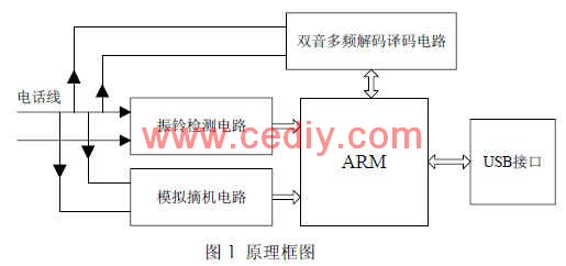
1. The system circuit is shown in Figure 1, including: ARM processor circuit with USB interface, ringing detection circuit, analog off-hook circuit and DTMF transceiver circuit;
This article refers to the address: http://

The system is connected to the computer through a USB interface, and the computer has a special user interface for the user to implement dialing, querying and the like. When the user dials the computer, the computer transmits the called number and call information to the ARM processor through the USB port. The ARM processor controls the analog off-hook circuit to pick up the phone, and starts the dual-tone multi-frequency transceiver circuit for dial-up connection. When a call comes in, the ringing detection circuit detects that the ringing is valid, and the user interface will prompt the user to “have an incoming call, please go off-hookâ€.
2. Introduction to DTMF technology The DTMF dual-tone multi-frequency system is a dialing method in wired telephone communication. It has the advantages of multi-function, low bit error, high reliability and fast speed. A dual tone multi-frequency signal (DTMF) is a combination of a set of low audio signals and a set of high audio signals in a certain way, each set of audio signals each having 4 audio signals, and each combination has a high audio signal and a Low audio signal, a total of 16 combinations.
The standard values ​​of the low audio signal are: 697 Hz, 770 Hz, 852 Hz, 941 Hz; the standard values ​​of the high audio signal are: 1209 Hz, 1336 Hz, 1477 Hz, 1633 Hz. The selection of the above standard frequency is not optional, but is designed to take into account the sound of dial tone, busy tone and AC power.
These noises are not within the range of the above DTMF signals, and in order to avoid harmonic interference between the standard frequencies, the highest standard frequency listed is less than the third harmonic frequency of the lowest standard frequency. Third, the composition of the hardware circuit The hardware circuit of the intelligent dialer is composed of ARM memory, ringing detection circuit, analog off-hook circuit and dual-tone multi-frequency transceiver circuit. The ARM processor is the core of the hardware circuit. It performs the functions of controlling and communicating with other circuits. The system selects the ARM-based 32-bit flash microcontroller AT91SAM7S64 introduced by ATMEL, which has low cost, low power consumption and rich externality. Set up resources, including a USB 2.0 device. The analog off-hook circuit is used to implement the analog off-hook function before the system dials, so that the switch determines that the system terminal has been off-hook, thereby sending a dial tone to the system terminal to prompt the user to dial; the ringing detection circuit completes the function of detecting whether the ringing is effective. If the ringing is effective, the ringing detection circuit sends a square wave signal to the ARM processor; the dual-tone multi-frequency transceiver circuit is the main circuit for implementing the dialing function. The hardware composition of each circuit is described in detail below.
Ringing detection circuit

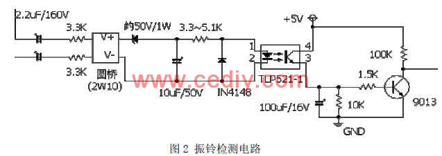
As is apparent from Fig. 2, the ringing detection circuit performs a function of detecting whether ringing is effective. When the user is called, the telephone exchange sends a ringing signal. The ringing signal is a sine wave of 25±3 Hz, and the effective value of the voltage is 90±15V. The ringing is in a period of 5 seconds, that is, 1 second pass, 4 seconds off. After the ringing signal is rectified by the circular bridge, the pulse signal is output by photoelectric isolation. The pulse signal is input into the 74LS04 to form a square wave signal, which is sent to the ARM processor [1].
2. Analog off-hook circuit

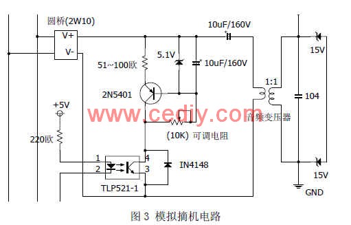
Figure 3 shows the function of the analog off-hook circuit to complete the off-hook before dialing and the automatic off-hook after the call. Since the polarity of the signal sent by the telephone line is not determined, the circular bridge can stabilize the polarity of the signal and output the output from the positive output forever. It is positive polarity, and the output of the negative output is always negative. The operation of the analog off-hook circuit is determined by the high-low level of the second pin of the optocoupler (TLP521-1) transmitted by the ARM processor. When the ARM processor transmits a low level, the optocoupler starts to work and stabilizes. The voltage diode is reverse-punctured and regulated at 5.1V. The triode (2N5401) is turned on because the base level is pulled low, and the loop current value suddenly increases. The telephone switch detects the current and changes the line voltage to a dozen. Volt DC, analog off-hook can be achieved. If the user does not dial, the 2 terminals of the optocoupler are always at a high level, do not work, the triode is not turned on, and the circuit loop exhibits high impedance. The audio transformer acts to isolate the high and low voltages, and the function of the right side of the circuit is to control the output signal to within +/-15V.
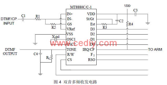
3. The dual-tone multi-frequency transceiver circuit takes into account the reliability of the hardware circuit. After referring to a large amount of data, the system selects the MT8880 chip to complete the dual-tone multi-frequency transceiver function. The MT8880 chip is professionally reliable, widely used, and easy to develop. The connection diagram of the dual-tone multi-frequency transceiver circuit is shown in Figure 4.

A dual-tone signal with a peak of about 1V can be obtained at the output of the amplifier. The MT8880 can receive various tones during the call and 16 dual audio signals. The receiving signal tone and the DTMF signal share the same channel, and the MT8880 cannot receive the DTMF signal and the signal tone at the same time, and is time-multiplexed. The signal tone and the DTMF signal are coupled to the coil, and then the signal on the telephone line is input to the input terminal IN- of the MT8880 via the electrolytic capacitor C1 and the resistor R1. The DTMF signal received and transmitted by the MT8880 is coupled by an analog off-hook circuit [2-5]. When MT8880 is used as the DTMF receiver, the signal transmitted from the telephone line is converted into a digital signal by MT8880, and is read by the ARM processor [6].
The use of dual tone multi-frequency (DTMF) technology enables remote data transmission tasks over telephone lines with the disadvantage of being too slow (about 80 baud). The system can realize the function of remote data transmission. It only needs to control the analog off-hook circuit after the system (called user) receives the ringing through software programming, realize the analog off-hook, and set the chip MT8880 to work in the receive data mode. After the calling user is in the call, MT8880 immediately enters the sending mode, waiting for the user to send data. Fourth, software programming This system realizes communication with some ports of MT8880 through software programming. The system uses IAR as the software development environment. IAR's Embedded Workbench series is an enhanced integrated embedded integrated development environment, which fully integrates the file editing, project management, compilation, linking and debugging tools needed to develop embedded systems. IAR's unique C-SPY debugger can not only perform pure software simulation of targetless hardware in the early stage of system development, but also integrate real-time online simulation debugging of user system by combining J-Link hardware emulator introduced by IAR. 3].
In the software programming, pay attention to the MT8880 power-on delay of more than 100ms, the register must be cleared before initialization to use [2].
1. DTMF receiving and command interpreter This program is the program after the system simulates off-hook. The ARM processor sends the called number to the MT8880 chip. Some programs are as follows. In order to facilitate the upgrade and development, there are detailed comments: Set MT8880 mode. For dual audio operation mode (send data), configure CRA=1101, CRB=0000
dBytesCRA[3] = 1;
dBytesCRA[2] = 1;
......
dBytesCRB[3] = 0;
......
MT8880_WriteCRACRB(dBytesCRA, dBytesCRB);//Write 1101,0000 to CRA and CRB respectively
dLength = strlength(pSendNum); //Save the length of the called number to be written to MT8880
For(dL = 0; dL < dLength; dL++) { //Continuously send dLength DTMF signals
Switch(*pSendNum++) { //Resume the character phone number from the ARM processor
Case '1':{
dBytesSend[3] = 0; //D3D2D1D0=0001
dBytesSend[2] = 0;
......
Break;}
Case '2':{
dBytesSend[3] = 0; //D3D2D1D0=0010
......
Break;}
......
Default:
{
Break;
}
}
MT8880_WriteDataReg(dBytesSend); //Write send data register
For(iTemp = 5000; iTemp; --iTemp) {
MT8880_ReadStateReg(dBytesSReg); //Read the value of the status register
If(dBytesSReg[1] == 1) //Check if the second digit of the status register is 1
Break; //that is, the send data register is full, ready to send data
}
2. The signal tone processing program first sets the chip MT8880 to call processing and interrupt mode. The signal tone processing program is divided into four parts: one is to detect whether dialing is allowed before dialing, that is, whether the detecting signal tone is a dial tone or a busy tone; Whether the detection is turned on after dialing, that is, whether the detection signal tone is a ringback tone, a busy tone or a busy tone; the third is to detect whether the response is answered after the dialing is turned on, that is, whether the ringback tone is detected to disappear; the fourth is to detect various signal tones: Dial tone, busy tone, ringback tone.
The characteristics of various signal tones: the dial tone is continuous in 5 seconds; the busy tone is 0.35 seconds in 5 seconds, 0.35 seconds off; the ringback tone is 1 second in 5 seconds, 4 seconds off.
3. The main function of the serial communication program is to receive the command of the host computer and perform the corresponding operation. I will write another article in detail.
V. Summary Firstly, the hardware composition of the smart dialer was studied and explained in detail, and some software codes were explained. The system has been tested and used. It has the characteristics of low cost, low power consumption, portability, and easy expansion of functions. It has a good use prospect in certain application backgrounds.
The author of this article is innovative: the system uses ARM7 as a microprocessor, low power consumption, simplified design, and easy to expand functions. USB is used as the interface between the modem and the peripheral computer and the computer, and the enumeration device is realized. The data transmission is stable and reliable, and is more convenient to use and carry than the serial interface.
Longkou Libo Insulating Material Co.,Ltd. , https://www.sdliboinsulation.com