[Source: High-tech LED " LED Good Products" magazine September issue (total 45th ) / Xiao Jinhua] General LED light source needs to use AC-powered driver to convert AC power line power into stable regulated DC power, To maintain a constant light output. The AC-DC LED driver needs to have electrical characteristics that match the LED, such as an output suitable for the LED forward voltage and drive current. Usually the driver is built on a separate PCB and connected to an LED PCB with an LED array.
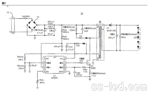
Figure 1 shows a typical circuit of an AC-DC LED driver utilizing a well-known flyback converter. The circuit 10 includes an AC power source 12 having a live (L) and neutral (N) terminals, and a rectifier circuit 14. When switch Q1 is turned on, current is drawn directly from the rectified sine wave. The energy is stored in the magnetic inductance of the primary winding of transformer T1. The rectifier diode D1 is reverse biased and the LED current is supplied by the secondary capacitor Cout. When Q1 is turned off, diode D1 is turned on and the stored energy is transferred to the secondary winding and output of transformer T1. The controller chip U1 may be, for example, an iW3620 digital PWM constant current controller for an AC/DC LED driver manufactured by iWatt, which adjusts the LED current to a constant reference value by comparing information about the secondary output voltage and the LED current. Where the information is reflected via the auxiliary winding of transformer T1 and based on the comparison, the duty cycle of switch Q1 is adjusted.
An AC-DC driver, such as that shown in Figure 1, is a complex large circuit. In order to manufacture simple circuits, LED manufacturers have developed AC LED circuits that are basically LED lighting circuits that operate on AC power, without the need for such a complex AC-DC driver as shown in FIG. However, the AC power line voltage is sinusoidal. Most AC LEDs operate directly in rectified mode, and their flicker frequency is double that of the AC power line frequency.
2 is a schematic diagram of a conventional AC LED circuit. In this circuit, the LEDs can be driven directly by the AC power source 102 without the use of complex converters. In the operation of the illustrated circuit, such as the positive half cycle of the sinusoidal AC power source V, the LED string S2 is reverse biased and the LED string S1 is turned on and illuminates. During the negative half cycle of the AC power source V, the LED string S1 is reverse biased, and the LED string S2 is turned on and emits light. The forward voltages of the LED strings S1 and S2 are equal. Resistor R limits the current flowing through LED strings S1 and S2.
>>>Unfinished , please refer to the September issue of Gaogong LED 's " LED Good Products" magazine.
Figure 1 shows a typical circuit of an AC-DC LED driver utilizing a well-known flyback converter. The circuit 10 includes an AC power source 12 having a live (L) and neutral (N) terminals, and a rectifier circuit 14. When switch Q1 is turned on, current is drawn directly from the rectified sine wave. The energy is stored in the magnetic inductance of the primary winding of transformer T1. The rectifier diode D1 is reverse biased and the LED current is supplied by the secondary capacitor Cout. When Q1 is turned off, diode D1 is turned on and the stored energy is transferred to the secondary winding and output of transformer T1. The controller chip U1 may be, for example, an iW3620 digital PWM constant current controller for an AC/DC LED driver manufactured by iWatt, which adjusts the LED current to a constant reference value by comparing information about the secondary output voltage and the LED current. Where the information is reflected via the auxiliary winding of transformer T1 and based on the comparison, the duty cycle of switch Q1 is adjusted.

An AC-DC driver, such as that shown in Figure 1, is a complex large circuit. In order to manufacture simple circuits, LED manufacturers have developed AC LED circuits that are basically LED lighting circuits that operate on AC power, without the need for such a complex AC-DC driver as shown in FIG. However, the AC power line voltage is sinusoidal. Most AC LEDs operate directly in rectified mode, and their flicker frequency is double that of the AC power line frequency.
2 is a schematic diagram of a conventional AC LED circuit. In this circuit, the LEDs can be driven directly by the AC power source 102 without the use of complex converters. In the operation of the illustrated circuit, such as the positive half cycle of the sinusoidal AC power source V, the LED string S2 is reverse biased and the LED string S1 is turned on and illuminates. During the negative half cycle of the AC power source V, the LED string S1 is reverse biased, and the LED string S2 is turned on and emits light. The forward voltages of the LED strings S1 and S2 are equal. Resistor R limits the current flowing through LED strings S1 and S2.

>>>Unfinished , please refer to the September issue of Gaogong LED 's " LED Good Products" magazine.

Solid State Relay,Relayrelay Electrical,Motor Overload Relay,Dc Coil Contactor
NanJing QUANNING electric Co.,Ltd , https://www.quanningtrading.com