The exciting applications of capacitive sensing technology that have recently appeared in the portable media player, notebook computer, and mobile phone markets have made people forget that such interface technology has been widely used in the design of household appliances. For many years. Significant advances in sensing algorithms and control circuits have made this technology suitable for more applications. Designers see the value of capacitive sensing technology-not only can replace mechanical buttons and membrane switches; but also can be applied to various novel applications, such as: touch screens and proximity sensors.
Sense capacitance
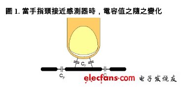
The capacitive sensor is composed of a conductor piece, a ground plane, and a controller. In most applications, the conductor piece will be a copper circuit board, and the ground will be filled with potting. There is a native (parasitic) capacitance (CP) between the two. When other conductive objects, such as fingers, approach the sensor, as the capacitance value (CF) of the object increases, the capacitance value of the system also increases. (Figure 1)

There are several ways to detect the increase in capacitance caused by CF. In the field effect measurement method, an AC voltage divider is used between the sensing capacitor and the system reference capacitor. By monitoring the change of current on the voltage divider, the capacitance value generated when the finger is touched can be sensed. Charge transfer uses a switched capacitor circuit and a reference bus capacitance value to repeat the charge transfer steps from the smaller sensor capacitor to the larger bus capacitor. There is a proportional relationship between the voltage value on the bus capacitor and the sensor capacitance value, so the voltage value is measured after a fixed number of steps, or by calculating the number of steps required to reach a certain voltage critical value Capacitance value. In addition, the relaxation oscillator (relaxaTIon oscillator) is a method of measuring the charging time, where the charging rate is usually determined by the value of the fixed current source and the sensor capacitance value. Larger sensor capacitors require longer charging times, and this part can usually be measured using pulse width modulators (PWM) and timers. As for the continuous approximation method (Successive ApproximaTIon) is also a method of measuring the charging time of the capacitor, the difference is that the starting voltage is determined by the continuous approximation method.
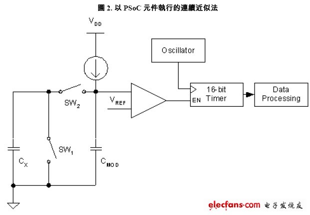
The continuous approximation method (patent filed by Cypress) implemented with PSoC components uses a set of capacitor-to-voltage converters and a single-slope analog-to-digital converter (ADC). The capacitance value measurement method is to convert the capacitance value to a voltage value, and then store the voltage value in a capacitor, and then use an adjustable current source to measure the stored voltage value. The capacitance-to-voltage converter uses switched capacitor technology. This circuit system allows the sensor capacitor to reflect the corresponding voltage value according to its capacitance. The frequency used by the switched capacitor is generated by the oscillator inside PSoC itself.
The sensor capacitor is connected to the analog multitasking bus and is charged by a programmable current output digital-to-analog converter (iDAC) also connected to the bus. The charging capacity on each bus is q = CV. When SW2 is open and SW1 is closed, the potential across CX is zero, and the power on the bus is reduced. The reduced value is proportional to the capacitance of the sensor. This charging and discharging action will be repeated all the time. At this time, the sensor capacitor will also become the current load on the bus. (Figure 2)

Through the operation of the switched capacitor circuit, iDAC will determine the constant voltage value on the bus by a binary search method. This voltage value affects the switching frequency of the switched capacitor, the sensor capacitance value, and the iDAC current value. The bus is actually equivalent to a bypass capacitor, which can stabilize the final voltage. Additional capacitors can also be added to the bus to adjust the circuit's behavior and timing.

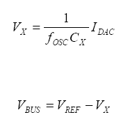
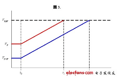
The calculated iDAC value is then used again to charge the bus and measure the charging time required by the bus from the initial voltage to the threshold voltage of the comparator. The initial voltage is in the absence of finger contact, so the charging time can be measured in advance. When the finger touches the sensor, it will increase the value of CX and reduce the initial voltage, so it will extend the charging time measurement. (As above formula and figure 3)

SGM7P type (rated speed: 3000r\/min) of inertia and flat servo motor in non speed reducer.
SGM7P
Wuxi Trenty Machinery & Equipment Co., Ltd. , https://www.elec-inverter.com