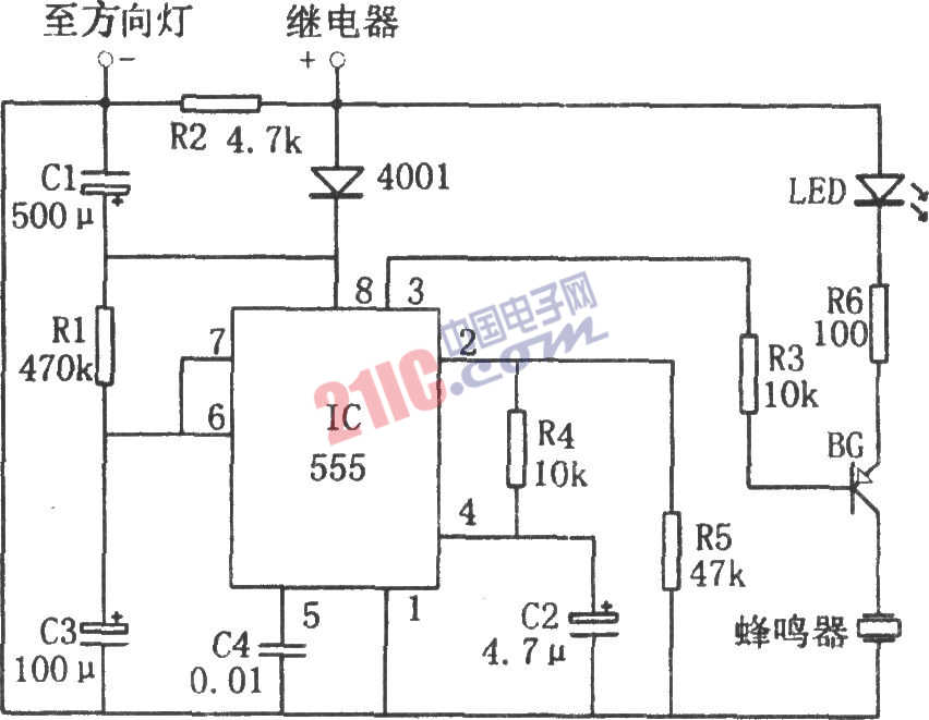
As shown in the figure is a light alarm circuit. The circuit consists of a monostable delay circuit, a driver circuit, a buzzer, a light emitting diode, and the like. The output signal of the one-shot delay circuit composed of 555 and R1 and C3 controls the operation of the following circuit.

After turning on the light, the power from the direction lamp relay is added to the 555 8 pin through the diode, and the capacitor C3 is charged through R1. With the progress of charging, the 6-pin potential rises. When the 6-pin potential reaches 2/3 VDD (approximately 1 minute delay), 555 is toggled. The low level of the 3 pin output turns on the BG. Correspondingly, the LED is driven to emit light, and the buzzer sounds. The sound and light signal prompts the driver to turn off the light in time.
The length of the light in the circuit corresponds to the delay time of the circuit, which can be changed by adjusting the time constant R1C3.
This circuit enables the driver to promptly turn off the power when the driver forgets to turn off the direction light.
Butt Connector,Lugs Insulated Female Connectors,Insulated Female Connectors,Non-Insulated Spade Terminals Wire Connector
Taixing Longyi Terminals Co.,Ltd. , https://www.lycopperterminals.com