| Transistor low-frequency amplifiers are mainly used to amplify low-frequency small-signal voltages, with frequencies ranging from tens of hertz to one hundred kilohertz |
| First, the bias circuit of the transistor |
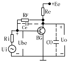
| In order for the amplifier to achieve linear amplification, the transistor must not only have a suitable static operating point, but must also stabilize the operating point. Due to the influence of temperature on the tube parameters β, Icbo and Ube, they are finally reflected in the change of Ic. In order to eliminate this effect, we stabilize the static operating point by the negative feedback of the DC or voltage biased by the transistor The two kinds of bias circuits and working point stability principle are as follows |
| Table I, | Bias circuit of transistor amplifier | ||||||||||||||||||
| |||||||||||||||||||
| Second, the three circuit forms of the amplifier |
| The amplifier is a three-terminal circuit, one of which must be the common “ground†terminal of the input and output. It is a common circuit, which is connected to the base and is called a common circuit. These three have different performances, see the table |
Three circuit forms and their performance comparison | ||||||||||||||||||||||||
|
| 3. Graphic method |
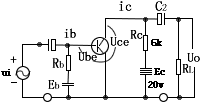
| The so-called graphical method is to use the input and output characteristic curves of the transistor to analyze the performance of the amplifier by drawing. The graphical method can intuitively and comprehensively indicate the working process of the transistor amplification, and can calculate some performance indicators of the amplifier. Examples to illustrate the graphical process of graphical methods, Example: Knowing the parameters and input voltage Ui = 15sinωt (millivolt) in the circuit shown in the figure below requires graphically determining the static operating point parameters Ibq, Icq, and Iceq of the circuit, and calculating the voltage and current amplification factors Ku and Kio. |
 |
Graphical steps |
| 4. Equivalent circuit method and h parameter |
| 1. The simplified "parameter change" of the equivalent circuit of the h parameter means that the Ib, Ube, Ic, and Uce of the transistor change only a small amount around the static operating point Q. Ib and Ube are the input variables of the transistor, and Ic and Uce are the output variables. If you regard the transistor as a two-port network with a controlled source, you can use four h parameters to simulate the physical structure of the transistor, so that the equivalent circuit of the h parameter of the transistor is shown in Figure 7-14. : hie = △ Ube / △ Ib ------- △ Uce = 0, --hfe = △ Ic / △ Ib ----- △ Uce = 0 hre = △ Ube / △ Uce ------ △ Ib = 0, --hoe = △ Ic / △ Uce ---- △ Ib = O Several parameters have their own physical meanings: hie is the input resistance when the output is short-circuited, that is, the reciprocal of the slope of the input characteristic curve; hfe is the current amplification factor of the short-circuit at the output, ie β (common emitter) or a (common Pole); hre is the internal feedback coefficient of the open circuit at the input terminal, which indicates the degree of the influence of the output voltage on the input voltage; hoe is the output conductance when the input terminal is open circuit, that is, the slope of the output characteristic curve. The two parameters of hoe are so small that they are negligible. Usually, two parameters of hie and hre are used to simulate the low-frequency transistor circuit. This is called a simplified equivalent circuit of h parameters, as shown in Figure 7-1-3. , Β is the above hie, hfe. The current amplification factor β (or hfe) can be obtained from the output characteristic curve or tested by the instrument, and the input resistance rbe is calculated by the following formula: rbe = rb + (β + 1) 26 (millivolt) / Ie (milliampere) In the formula: Rb is the base resistance, about a few hundred ohms, Ie is the static emitter current. The method to find the micro-variable equivalent circuit of the transistor amplifier is as follows: (1) The equivalent of the transistor shown in Figure 7-1-3 Analog type replacement; (2) All DC power supplies, DC blocking capacitors and bypass capacitors are regarded as short circuits; (3) Other components are drawn according to their original relative positions, The equivalent circuit can be used to find the amplifier's amplification factor, input resistance, output resistance, and analyze the frequency characteristics of the amplifier. |
 |
 |

Follow WeChat

Download Audiophile APP

Follow the audiophile class
related suggestion
1. Broadband amplification


