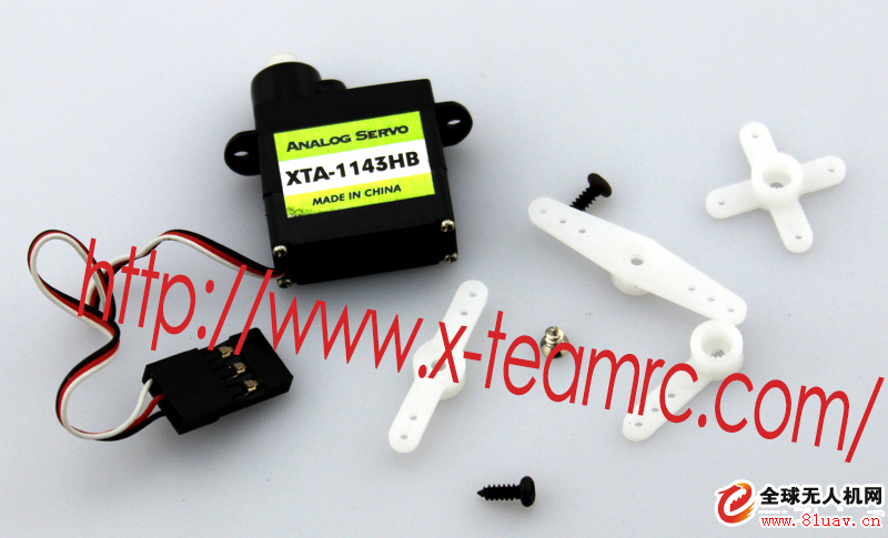
Its working principle is:
The control signal enters the signal modulation chip from the channel of the receiver to obtain a DC bias voltage. It has a reference circuit inside, which generates a reference signal with a period of 20ms and a width of 1.5ms, and compares the obtained DC bias voltage with the voltage of the potentiometer to obtain a voltage difference output. Finally, the positive and negative voltage output of the voltage difference to the motor drive chip determines the forward and reverse of the motor. When the motor speed is constant, the potentiometer is rotated by the cascade reduction gear, so that the voltage difference is 0, and the motor stops rotating.

The picture above shows the X-TEAM steering gear series.
Steering gear control: The control of the steering gear generally requires a time base pulse of about 20ms. The high level part of the pulse is generally the angle control pulse part in the range of 0.5ms~2.5ms. Taking the 180 degree angle servo as an example, the corresponding control relationship is this:
0.5ms--------------0 degrees;
1.0ms------------45 degrees;
1.5ms------------90 degrees;
2.0ms-----------135 degrees;
2.5ms-----------180 degrees;
This is only a reference value. For the specific parameters, please refer to the technical parameters of the steering gear.
Servo drive applications:
1. High-end remote-controlled simulation car, including at least the left turn and right turn functions, high-precision angle control, will inevitably give you the most realistic driving experience.
2. Multi-degree of freedom robot design.
3. Multi-way servo RC control, electric remote control aircraft, oil-powered remote control aircraft, navigation models, etc.
Solar Controller,Solar Charge Controller,Solar Intelligent Controller,Solar Tracker Controller
Fuzhou Mei Li Cheng Imp&Exp Co., Ltd , https://www.mlc-solar.com