introduction
Modern integrated operational amplifiers (op amps) and instrumentation amplifiers (in-amps) offer many benefits to design engineers compared to discrete devices. Although it provides many clever, useful and attractive circuits. This is often the case, and some very basic problems are overlooked due to the hasty assembly of the circuit, resulting in the circuit not being able to perform the intended function - or may not work at all.
This article will discuss some of the most common application issues and give practical solutions.
Missing DC bias current loop when AC coupling
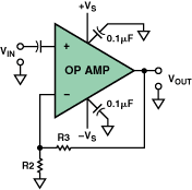
One of the most common application problems is the absence of a direct current (DC) loop that provides a bias current in an alternating current (AC) coupled operational amplifier or instrumentation amplifier circuit. In Figure 1, a capacitor is placed in series with the non-inverting input of the op amp for AC coupling, a simple way to isolate the DC component of the input voltage (VIN). This is especially useful in high gain applications where even small DC voltages at the op amp input limit the dynamic range and even cause output saturation. However, adding a capacitive coupling to the high-impedance input without providing a DC path for the current at the non-inverting input can cause problems.

Figure 1. Wrong op amp AC coupled input
In effect, the input bias current flows into the coupled capacitor and charges it until it exceeds the nominal value of the common-mode voltage of the amplifier input circuit or limits the output. Depending on the polarity of the input bias current, the capacitor will charge to the positive or negative voltage of the power supply. The closed loop DC gain of the amplifier amplifies the bias voltage.
This process can take a long time. For example, a field effect transistor (FET) input amplifier with a charge current I/C of 10-12/10-7=10 μV/s when a bias current of 1 pA is coupled to a 0.1 μF capacitor, or 600 μV minutes. If the gain is 100, the output drift is 0.06 V per minute. Therefore, general laboratory testing (using an AC-coupled oscilloscope) does not detect this problem, and the circuit does not experience problems until after a few hours. Obviously, it is very important to avoid this problem altogether.

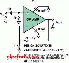
Figure 2. Correct dual-supply op amp AC-coupled input method
Figure 2 shows a simple solution to this common problem. Here, a resistor is connected between the input of the op amp and ground to provide a ground loop for the input bias current. In order to minimize the offset voltage caused by the input bias current, when using a bipolar op amp, the bias current of the two inputs should be equal, so the resistance of R1 should normally be set equal to the parallel resistance of R2 and R3. value.
However, it should be noted that this resistor R1 always introduces some noise into the circuit, so a trade-off is made between the circuit input impedance, the size of the input coupling capacitor, and the Johnson noise caused by the resistor. Typical resistor values ​​are typically between 100,000 Ω and 1 MΩ.
usb cable, usb-c types, usb c charging cable, best charging cable for iphone, usb c cable
TOPNOTCH INTERNATIONAL GROUP LIMITED , https://www.micbluetooth.com