Microwave notes introduce various common microwave RF circuit design methods in the form of design examples, one original per week. Subsequent launch of bridges, switches, and shifting equivalents. If you want to see content or technical issues, you can write a message at the end of the article. The microwave radio frequency network will select a user who gets the most comments from each message and give away the industry books. The prize for this issue is the book "Microstrip Circuit".
The 3dB bridge is very popular in microwave circuits. The 90° 3dB bridge can generate IQ signals, and the bridge belongs to the core circuit in devices such as phase shifters and delay equalizers. However, the conventional microstrip two-wire coupling circuit is difficult to realize ultra-wideband and strong coupling bridge. At the same time, since the effective dielectric constant of the odd-mode mode of the microstrip coupling line is different, even if strong coupling can be realized, the signal is in the odd-even mode circuit. The phase velocities are inconsistent, and the stronger the coupling, the greater the phase velocity difference, and the worse the performance of the bridge.
The Lange bridge is very popular in microstrip circuits, which are compact and can achieve broadband strong coupling in microstrip structures. In terms of feature parameter acquisition, the cross-joint multi-line coupling of the lange bridge is much more complicated than the conventional two-wire coupling, which also brings certain difficulties to the lange bridge design. This paper introduces a simple design method of the lange bridge.
1. Basic principle of broadband coupled bridge
The theory of broadband coupled transmission line coupler explains the contents of Chapter 15 of the book "Modern Microwave Filter Structure and Design". The coupled transmission line coupler and equivalent circuit are shown in Figure 1. The book has the following views on multi-section coupler cascades:
The circuit of the multi-section coupled transmission line Directional Coupler is equivalent to the 1/4 wavelength multi-section impedance conversion filter circuit; for the symmetrical type, the number of coupled line segments must be an odd number, and for the asymmetric type, the number of coupled line segments can be any node; The transmission of the coupler is equal to the transmission of the impedance transform filter, and the coupling of the coupler is equal to the echo of the impedance transform filter.
The coupling path and the transmission path of the coupled transmission line directional coupler are 90° out of phase.
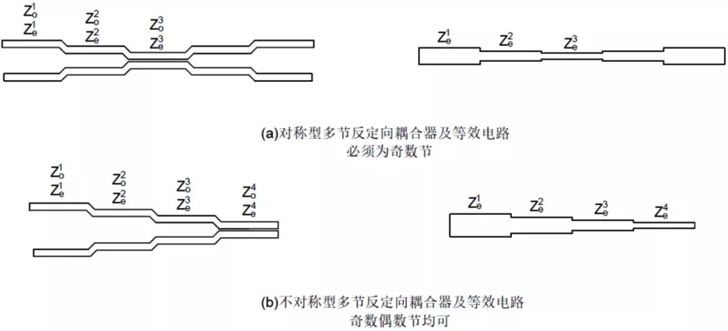
Figure 1. Schematic diagram and equivalent circuit of directional coupler for multi-section coupled transmission line
2. Superposition principle of coupled transmission line coupler
If several matching directional couplers are cascaded, they will act like a directional coupler after cascading, and the cascaded response conforms to the angle superposition principle. The superposition principle of the coupler is detailed in the implementation of the Bezier Waveguide Directional Coupler. When the coupled line directional coupler is superimposed, the port needs to be folded, as shown in Figure 2.

Figure 2, coupled transmission line coupler coupling degree superposition diagram
3, Lange bridge principle
The core of the Lange bridge is to replace the common two-wire coupling with a multi-wire (common 4-wire) coupling to achieve strong coupling in the microstrip planar circuit. The common form of the lange bridge is shown in Figure 3. It is recommended that the lange bridge is better:
Interdigitated Stripline Quadrature Hybrid lange "Simplified Design of Lange Coupler" DARKO KAJFEZ, "Design Equations for an Interdigitated Directional Coupler" WEN PIN OU
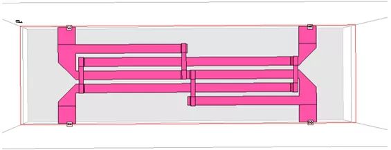
Figure 3. Lange bridge model
The latter two are the theoretical guidance of the lange bridge design. The core of the theory is to combine the multi-line coupling into a two-line coupling. The individual tried the equivalent method in the Simplified Design of Lange Coupler, but the equivalent result was poor. . Here, a relatively simple and accurate equivalent method of multi-line coupling and two-wire coupling is adopted. The method steps are as follows:
1) Electromagnetic simulation software simulation to obtain multi-line SNP
2) The model of Figure 4 is established in ADS, so that the response of the two-wire coupling is the same as the response of the multi-line coupling. The equivalent parameters of multi-line and double-line can be obtained through the optimization function of ADS.
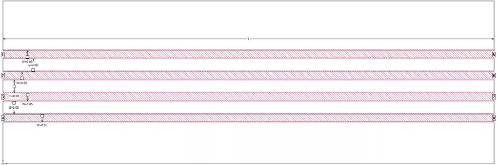
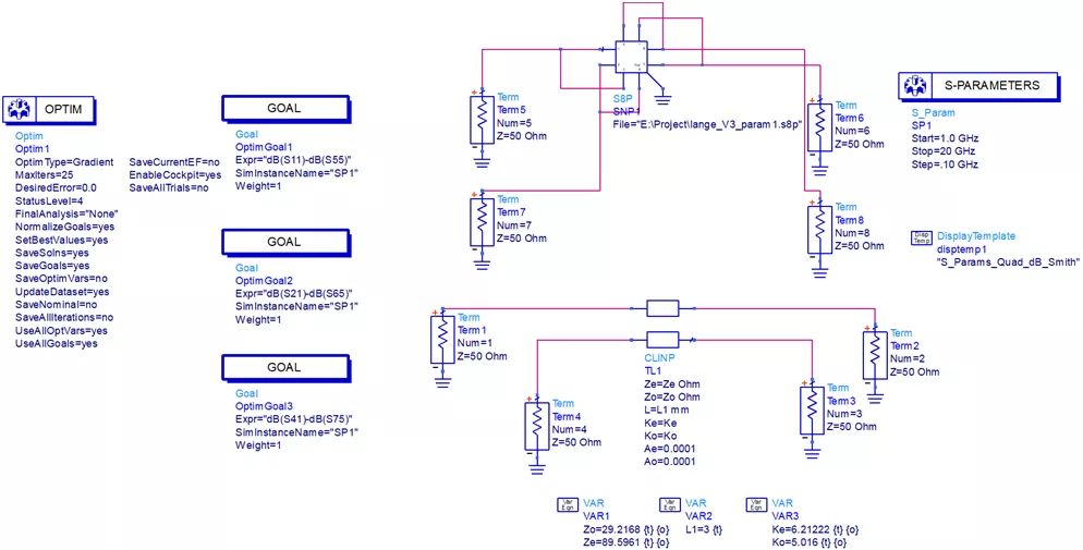
Figure 4. Multi-line coupling equivalent parameter extraction for two-wire coupling
4, the design of the Lange bridge
The coupling transmission line coupler is designed to follow the following steps:
1) Determine the number of coupled transmission lines and the odd-even mode impedance according to the indicator table or in the circuit simulation software such as ADS. 2) Calculate the physical size of each coupled transmission line according to the odd-even mode impedance. 3) Electromagnetic field simulation optimization
Here we use a lange bridge design of 6~18GHz-8.343dB (two cascades can be -3dB bridge) as an example to introduce the design method of ultra-wideband lange bridge.
· Coupling transmission line number and parity mode impedance determination
In the ADS, the symmetric coupled transmission line coupler model shown in Figure 5 is established. If the coupling degree is maintained at -8.343dB in the 6~18GHz bandwidth, at least three sections are needed. The parameters of each section are shown in Table 1.
Table 1, number of transmission line sections and odd-even mode impedance
| First quarter | Second quarter | Third quarter | |
| Odd mode impedance | 47 | 29.2 | 47 |
| Even mode impedance | 55 | 89.6 | 55 |

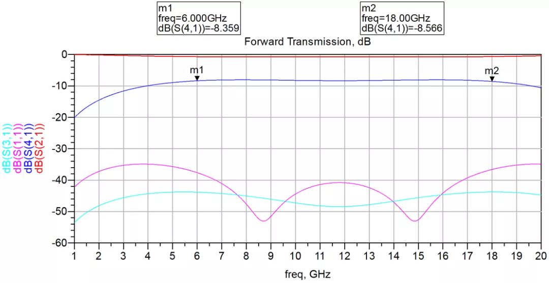
Figure 5. Coupled line number and odd-even mode impedance calculation model and results
· Determine the actual physical size based on the ideal parity mode impedance
According to the odd-even mode impedance of Table 1, it can be seen that the first and third sections are weakly coupled, and the two-wire coupling can be directly adopted. The second section is strongly coupled with 4-wire coupling.
For two-wire coupling, the actual physical size can be calculated by polar Si9000 software or other impedance calculation software.
For the 4-wire coupling of the second section, the physical dimensions of the 4-line are obtained by the parameter extraction method described above. The physical dimensions of the coupled transmission lines of each section can be obtained by calculation.
Table 2. Actual physical dimensions determined from ideal parity mode impedance
| Ideal impedance | First quarter | Second quarter | Third quarter | L is approximately equal to 2.5mm | |
| Odd mode impedance | 47 | 29.2 | 47 | ||
| Even mode impedance | 55 | 89.6 | 55 | ||
| Actual size | Types of | Two-wire coupling | 4-wire coupling | Two-wire coupling | |
| W(mm) | 0.35 | 0.05 | 0.35 | ||
| S(mm) | 0.7 | 0.1 | 0.1 |
· Electromagnetic field simulation optimization
The model is built in the sonnet according to the physical dimensions of the coupled transmission line coupler obtained above, as shown in Fig. 6. In order to make the coupler easy to cascade, a folding type is adopted. The model has not been specially optimized. The structure of the first simulation of the above parameters is shown in Figure 6. It can be seen from the results that the initial value obtained by the above design method is very accurate. It is believed that the coupler can achieve a better response with several iteration adjustments.
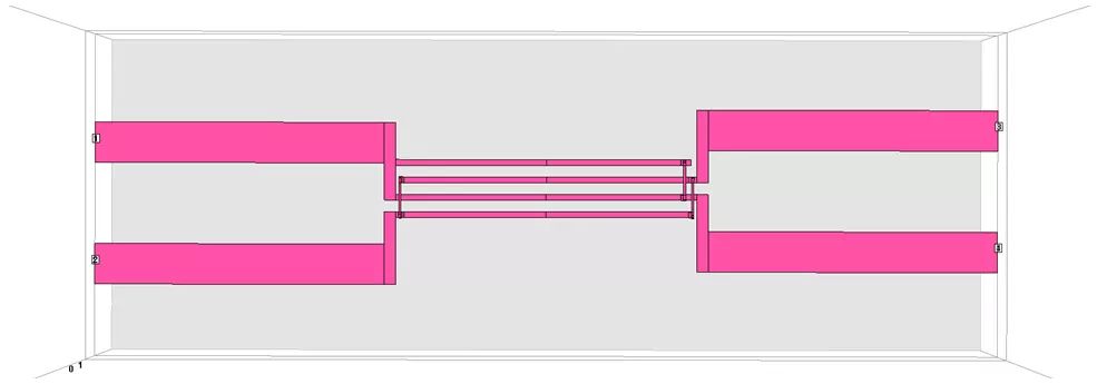
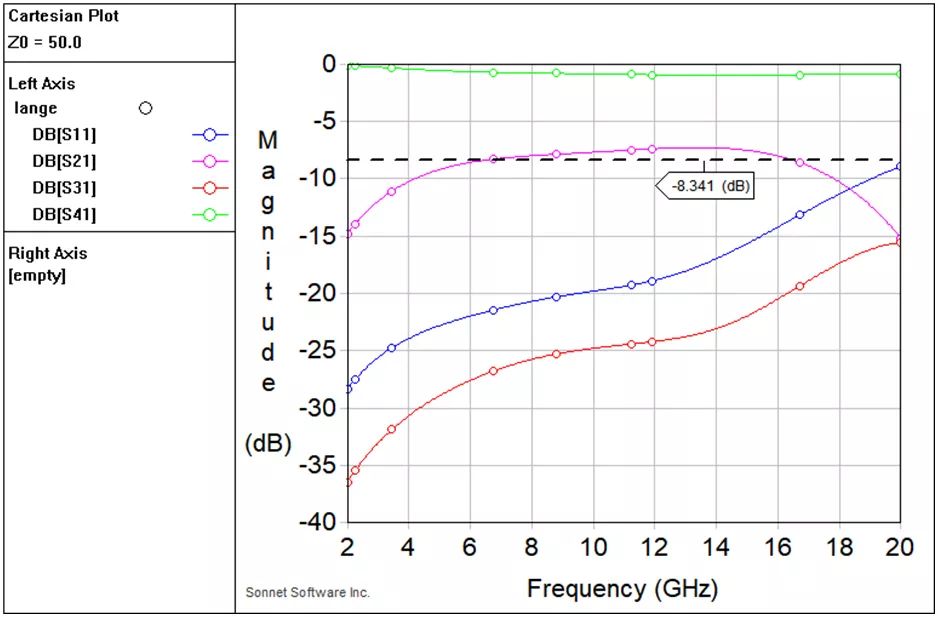
Figure 6. Model and results of the broadband-8.343dB lange bridge
After obtaining an ideal -8.343dB coupler, a coupler can be cascaded to obtain a -3dB coupler. The lange bridge design in the example is consciously different from the common lange bridge structure. I hope that the design of the lange bridge can be more deeply understood by thinking about this difference.
Zysen offer RF Reflective Type Switches, 2 to 16-way, controlled by TTL, minimum isolation 60dB. Customized frequency and optimized specifications available. Contact us with your requirement.
Reflective Switches,Microwave Pin Diode,High Frequency Switch,High Frequency Switching Transistor
Chengdu Zysen Technology Co., Ltd. , https://www.zysenmw.com