With the popularity of various mobile multimedia audio and video applications on mobile platforms, mobile phone users are increasingly demanding bandwidth. Many countries around the world, including government and communications companies, have been actively investing in the technology and standards of the next generation of fifth-generation mobile communications (5G). It was originally expected to complete the phase-1 standard formulation in the middle of 2018, and the phase-2 standard was completed before the end of 2019, and the time course for commercial promotion in 2020 also had an early trend. At present, 3GPP has conducted intensive discussions on the research project phase of the 5G standard. It is expected that the “work project†phase will be completed by the end of 2017, and the phase-0 standard will be produced.
In order to meet METIS's 2020 usage scenarios, the highest peak transmission rate must be 10 to 100 times the current transmission rate; the mobile data capacity must be 1000 times that of 2010 (as shown in Figure 1).
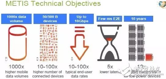
Figure 1. METIS 5G Technical ObjecTIves
To achieve the highest peak transmission rate defined by METIS and 1000 times the mobile data capacity, there are several main technologies as shown in Figure 2: increasing available bandwidth, increasing spectral efficiency, and increasing network density, among which to increase the available bandwidth is The most direct and easiest way to increase transfer rate and data capacity. But since it is mainly used in wireless communication at present. There are many standards and applications in the sub-6 GHz (sub-6 GHz) band, such as second generation mobile communication (2G), third generation mobile communication (3G), fourth generation mobile communication (4G), Bluetooth, wireless regional network. Wait, it will be increasingly difficult to find a bandwidth that can support larger capacity and higher transmission rates. Therefore, at present, large manufacturers around the world have reached a consensus on the use of millimeter-wave bands for 5G, in addition to the continuous evolution of the existing fourth-generation mobile communication technology; another road that uses the revolutionary technology development of the millimeter-wave band is also defined (as shown in the figure). 3)).
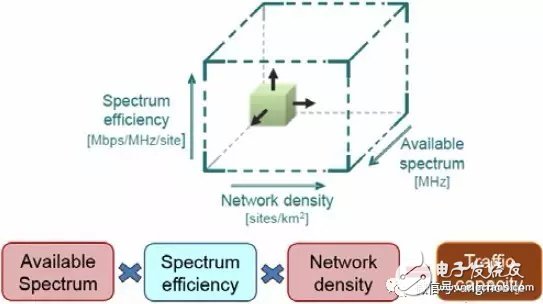
Figure 2. Approaches of increasing Traffic Capacity

Figure 3. 3GPP 5G Standardization Time Line
Second, the status quo of 3GPP millimeter wave communication standardThe time schedule for the development of 5G millimeter wave related standards currently planned by 3GPP and the world's major communication companies is expected to complete the phase-1 standard formulation in the middle of 2018, except for the frequency band less than 6 GHz (sub-6 GHz). In addition, the millimeter-wave band to 30 or 40 GHz will be covered; the phase-2 5G standard covering the 100 GHz band will be completed by the end of 2019 (as shown in Figure 3).
Although the millimeter-wave band provides a fairly large available spectrum to meet the bandwidth requirements of METIS for the highest peak transmission rate in 2020 and 1000 times the mobile data capacity, it also includes many millimeter-waves facing new high frequencies in outdoor communications. The challenges of wireless access technology, such as high path transmission loss, wall penetration, attenuation in the rain, and even transmission loss due to moisture and oxygen absorption, have long been suspected of the suitability of millimeter waves. It is a communication band of 5G.
At present, 3GPP and the world's major communication manufacturers have completed preliminary measurement of several major millimeter wave communication frequency bands, and announced the technical report TR38.900 on the millimeter wave channel model in early 2016, in addition to clarifying and proving The millimeter wave band is used as a 5G operating band for outdoor communication, and serves as a common basis for the development of 5G millimeter wave communication systems worldwide. The ITU-R has announced candidate bands for 5G millimeter waves (as shown in Figure 4) at the WRC-15 meeting in October 2015, covering eight bands from 24.25 GHz to 86 GHz. In the United States, FCC also pre-empted four millimeter-wave bands of nearly 11 GHz bandwidth, such as 27.5~28.35 GHz, 37~38.6 GHz, 38.6 GHz~40 GHz, and 64-71 GHz, as shown in Figure 5, in July 2016. To accelerate the development and deployment of 5G millimeter wave communication systems by US telecommunications vendors.
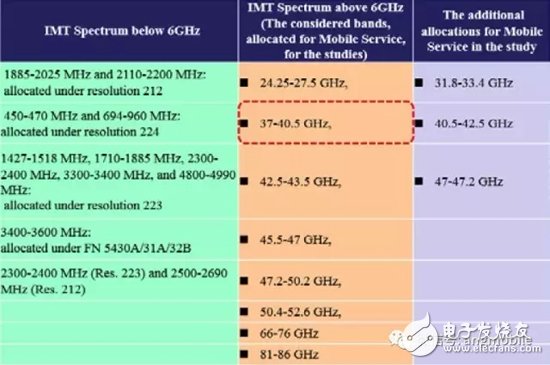
Figure 4. ITU-R IMT Spectrum
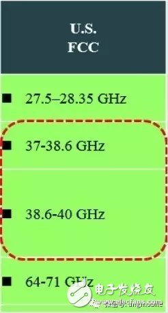
Figure 5. USFCC 5G mm-wave Spectrum
Third, the main challenge of high-frequency access to millimeter wave communicationMillimeter waves have several major high-frequency wireless access challenges in outdoor communications, as shown in Figure 6. The following is a detailed description of the challenges of these major millimeter-wave high-frequency wireless access.

Figure 6. Key Challenges of Millimeter Wave Radio Access
1. Beamforming technology
To solve these high-frequency wireless access problems of millimeter wave in outdoor communication, the solution is to design a large number or a large number of antenna arrays, and the antenna arrays are forwardly coupled through the appropriate design of the antenna array. To greatly increase the antenna gain. At this time, the radiation pattern of the array antenna after forward coupling will become a thin radiation beam and have a larger antenna gain. This is called beamforming technology, as shown in FIG.
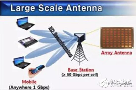
Figure 7. Large or multiple antenna array beamforming techniques
The beam formed by the antenna array has a half-power beamwidth of the beam that is narrower as the number of antenna elements in the antenna array increases, and the gain of the array antenna is also larger. Each time the number of antenna elements in the antenna array is doubled, the gain of the array antenna is increased by 3 dB.
By designing a large or large number of antenna arrays to provide a large array antenna gain to compensate for various transmission losses of high-frequency communication, it is possible to achieve the coverage of a small cell (Small Cell) with a transmission area of ​​100 to 200 meters. .
2, beam tracking technology
However, because the beam formed by the antenna array has a half-power beamwidth that is narrower with the number of antenna elements in the antenna array, the manner of transmitting in the omnidirectional direction of the sub-6 GHz low frequency band is changed in the original 4G or before. It becomes a directional transmission. Under the typical situation that the mobile communication terminal user will move, the problem of alignment is derived; that is, how to make the beam formed by a large or huge number of antenna arrays move with the end user. Mobile to provide mobile transmission and always maintain good communication quality, which is achieved by the design of the beam tracking algorithm, as shown in Figure 8.
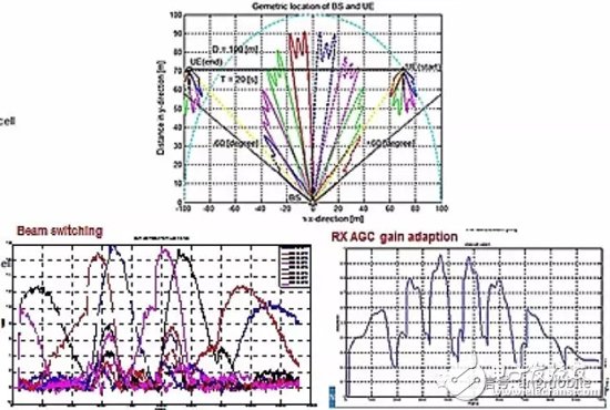
Figure 8. Beam Tracking Algorithm supporting UE Mobile Transmission
3, blocking the problem
As mentioned above, the millimeter wave in outdoor communication must utilize a phase antenna array composed of a large number of antenna elements to form a narrow beam transmission, and overcome the high path loss and transmission loss of outdoor communication with high array gain. However, the most difficult problem of narrow beam directivity transmission of such beamforming is the blocking problem, especially for the 5G enhanced mobile broadband (eMBB) application defined by 3GPP. The main application scenarios are crowded crowds such as shopping malls and plazas. The hot spot, as shown in Figure 9, is even more difficult to avoid. The 5G WeChat public platform (ID: angmobile) learned that the author further pointed out that once the signal is blocked, it will generate tens of dB of signal power loss, which will greatly reduce the transmission quality and even continue communication. Therefore, the blocking problem must be solved in order to enable the 5G enhanced mobile broadband application to become an actual achievable 5G application scenario in these scenarios.

Figure 9. 3GPP 5G Millimeter Wave eMBB Typical Application Scenarios
4, multi-user terminal support
Another thorny problem of forming a narrow beam directional transmission using a phase antenna array composed of a large number of antenna elements is the problem of supporting a plurality of user terminals.
For a small cell (Small Cell), the more user terminals can be supported at the same time, the lower the system construction cost. Therefore, the phase antenna array must support multiple user terminals in the hotspot.
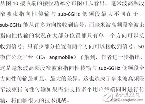
As shown in Figure 10, the ITRI is aimed at a typical metropolitan area with densely populated buildings and high-rise buildings at both ends: the channel measurement results of the street canyons, and the received power distribution maps at the receiving ends of several different receiving locations.
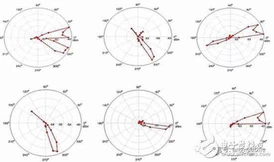
Figure 10. Received Power Profile of mm-Wave Channel Measurement in Street Canyon Scenario
ITRI ​​has been investing in the development of 5G high-band access technology since 2014. The first plan chose the 11GHz band as the planned goal of the forward-looking plan because of the ease of accessibility of the parts. Completed the design and implementation of standard development, system design specification design, system simulation platform construction, system performance floating point and fixed point simulation, system architecture design, and media access control layer (MAC) software in one year. Design and implementation of frequency unit, design and implementation of RF front-end circuit, design and implementation of 2x8 16 antenna unit base station antenna array and 2x2 antenna unit user terminal antenna array, system integration and verification, completed the first carrier aggregation in Taiwan The 5G hardware and software verification platform with a technical bandwidth of 250MHz and a peak transmission rate of up to 1Gbps is shown in Figure 11. In December 2014, he went to Texas to participate in the international exhibition of IEEE GlobeCom-2014, as shown in Figure 12.
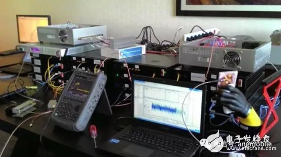
Figure 11. ITRI 11GHz 5G HW/SW Verification Platform
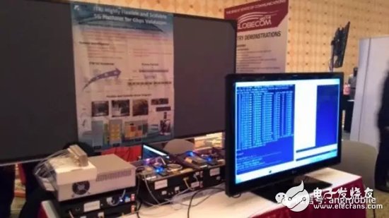
Figure 12, ITRI 11GHz 5G HW/SW Verification Platform Demonstrated in IEEE Globecom-2014
In 2015, in cooperation with the Science and Technology Development Department of the Ministry of Economic Affairs of Taiwan, the implementation of the “38GHz millimeter wave band†high-frequency access technology plan was launched. This plan was also approved by Taiwan’s mobile phone chip manufacturer MediaTek, and signed a technical license of NT$10 million. At the same time, the manpower and the ITRI team worked together to develop the design specifications and jointly developed and verified the base station phase antenna array including the uplink/downlink, 8x8 64 antenna elements, the user terminal phase antenna array of the 8x4 32 antenna unit, and the hybrid type. The RF front-end of the beamforming architecture, beam tracking algorithm design, peak transmission rate up to 1Gbps, support for 5G millimeter wave hardware and software verification platform greater than 10km/hr mobile transmission and 200m coverage, as shown in Figure 13. ITRI ​​and MediaTek jointly went to Barcelona, ​​Spain in February 2016 to participate in the international exhibition of MWC-2016, as shown in Figure 14.
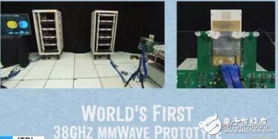
Figure 13, ITRI 38GHz mm-wave 5G HW/SW Verification Platform
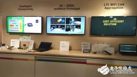
Figure 14. ITRI 38GHz mm-wave 5G HW/SW Verification Platform Demonstrated in MWC-2016
V. Conclusion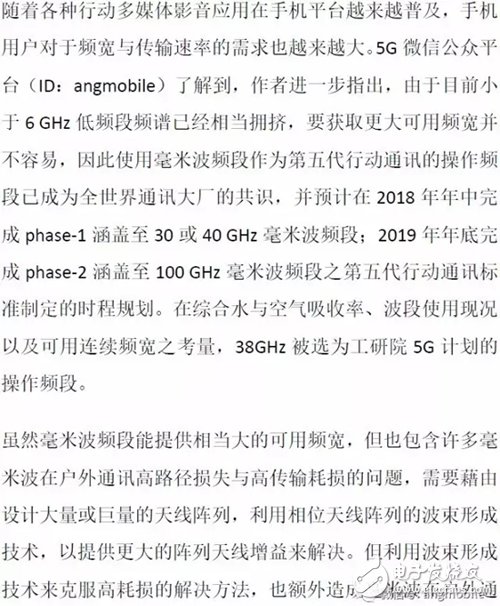
iDealTek-Electronics has accumulated rich application experience and design technical knowledge in the field of High-voltage power supplies, from Linear High Voltage Power Supplies based on power frequency transformers to Switching High Voltage power supplies based on IGBT components, from 60KV, 1KW High Voltage Power Module, to 5KV ~ 40KV, 1KW 2U Laboratory High-voltage power supplies, and to 5KV ~ 60KV, 2KW 4U and 5KV ~ 100KV, 6U rack-mounted capacitor charging high-voltage power supplies, and then to floor-standing cabinet-type high-current high-power high-voltage power supplies, all our high voltage power supplies are featured for high reliability, excellent high-voltage output stability and low-ripple electronic characteristics.
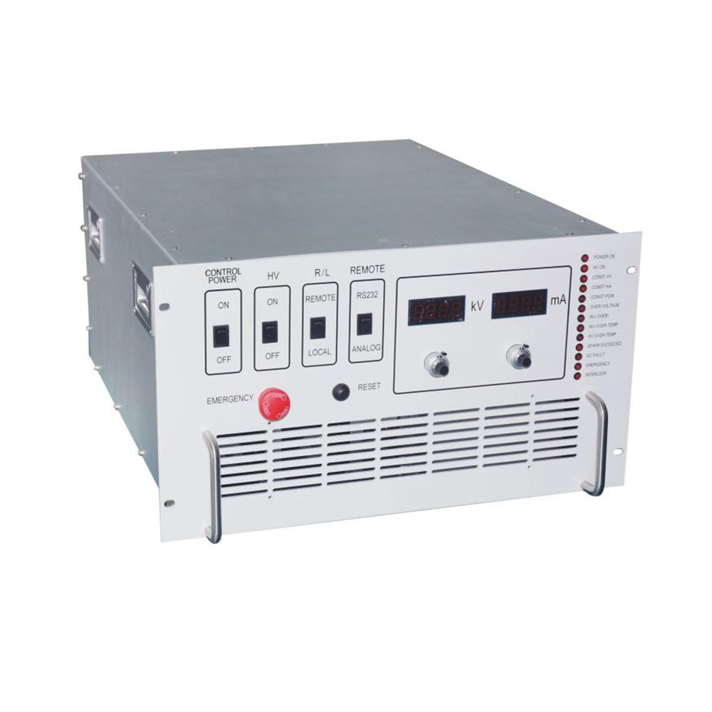
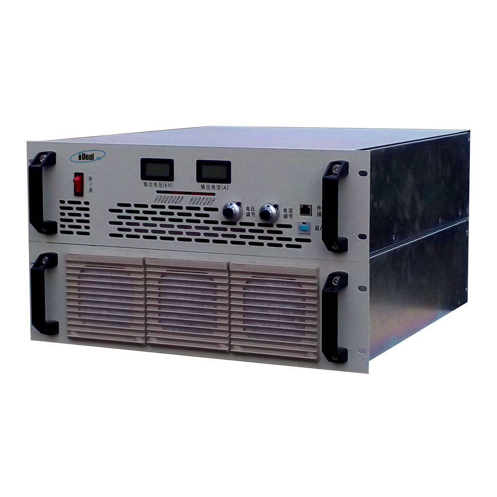
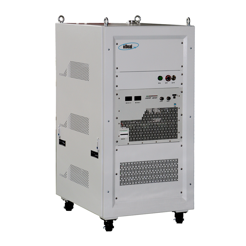
Through the reliable and durable operation panel on the front panel of the high-voltage power supply, the output voltage and current can be easily set and controlled. The high-precision LED or LCD ensures intuitive and high-precision high-voltage output measurement functions. Our high-voltage power supplies can be equipped with a wealth of remote-control interfaces, such as RS232 / RS485 /DB15 / DB25 / DB50 analog signal interface, etc. for remote high-voltage enable and inhibit, high-voltage output control programming and data monitoring.
Our HV power supplies have complete built-in protection functions, such as overvoltage protection, ARC protection, load discharge protection, over heat protection, etc. The protection mechanism can start in transient time to ensure the safety and reliability of the power supply itself and customer loads under high-voltage output.
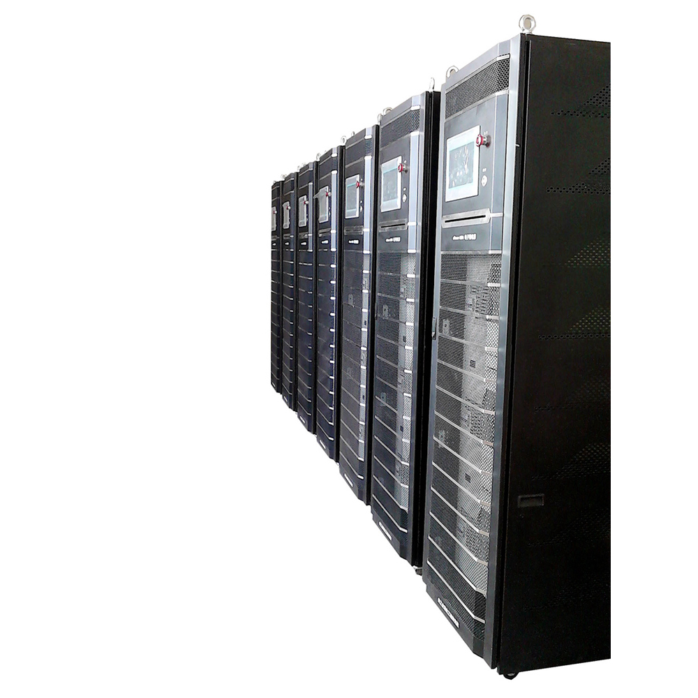
At present, our high voltage power supplies are widely used in high-voltage laboratories, capacitor charging, electron beam, ion implantation, FUSION power generation and other industries.
HV Power Supplies, High-voltage Power Supplies, High Voltage DC Power Supplies, HV PSU, High Voltage Power Module
Yangzhou IdealTek Electronics Co., Ltd. , https://www.idealtekpower.com