When making audio speakers, most of the frequency dividers use commercially-available finished products, but the frequency dividers sold on the market are uneven, and the quality is mostly more than one hundred yuan, which is not acceptable to junior enthusiasts. The quality of the frequency divider whose price is below tens of yuan is difficult to guarantee, and the actual use is mediocre. The self-made frequency divider can be used for less investment in exchange for larger gains. After practice, the author explored the method of making frequency dividers in amateur, and used self-made frequency dividers to perform well in the sound system.
1. Material preparation According to the design of the frequency divider schematic, prepare the following materials:
1. According to the requirements of the inductance coil, select the non-metallic skeleton, such as solder wire, plastic skeleton of the raw tape for sealing, and other wooden and colloidal skeletons.
2. Select the enameled wire with appropriate thickness and high quality (I chose the enameled wire removed from the starter switch of the car).
3. Resistor-capacitor parts choose capacitors and resistors with appropriate capacity, resistance and power according to circuit requirements. It is best to use imported or domestic high-quality CBB capacitors for frequency-dividing capacitors. High-power cement resistors are the first choice for resistors.
4. Adhesive This agent can be selected from commercially available "Ridoku" and other strong viscosity adhesives.
5. For coins and bolts, choose a copper product with a diameter of about 4 mm, and the length depends on the height of the inductor frame.
6. According to the number of frequency-divided components, choose a high-quality copper-clad plate of appropriate size. The direction of the circuit is carved with a utility knife according to the design requirements.
7. A plate of transparent tape.
2. Production 1. Around the inductor, drill a small hole with a diameter slightly larger than the enameled wire in the middle of the top and bottom of the adhesive bottle (because the liquid is viscous, it will not flow out of the hole), and wear a piece of plastic hose in each hole , Put the enameled wire through the two hoses to ensure that the enameled wire will not be scratched when passing through the two holes, and then one person will tighten the end of the enameled wire, and the other person can take the other end of the enameled wire and wind it on the skeleton. Enameled wire, because the enameled wire has been evenly coated with a layer of adhesive when passing through the adhesive, you can use your hands to pinch the two ends of the skeleton to rotate it. After the number of inductance turns around, cut off the extra enameled wire and fix it. Lead out the wire, and after the adhesive on the wire solidifies, wrap several layers tightly on the coil with transparent tape.
2. Component installation According to the position of the inductance coil and the resistance-capacitance piece on the board, make a hole in the board with a small drill, drill a hole slightly larger than the diameter of the copper bolt in the middle of the coin, and then pass the copper bolt through the coin Coil and circuit board, and then pad with spring washer, fasten with nut, scrape the coil, capacitor and resistance leads to tin, solder them to the corresponding position, and finally solder the incoming and outgoing wires on the board.
After the above operation, a high-quality and inexpensive crossover is completed, and the rest is the joy of success.
Inductor wiring of the frequency divider pays attention to the connection method of the inductance coil in the frequency divider of the speaker, which has a great influence on the sound quality and timbre. The pair of inverting speakers used, the inductive coil connection method is the outer circle into the inner circle (pictured), the sound is balanced and round. I used the inner circle to the outer circle connection, but the bass was completely absent.

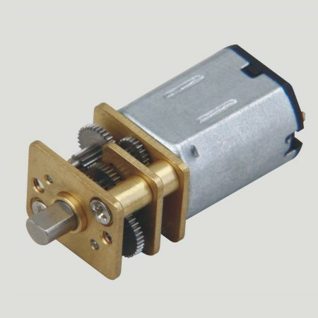
Door Lock Motor Characteristics 1. No direction: don't need to distinguish the door direction, left and right sides, both inside and outside the door, can be universal. (convenient purchase locks and reduce inventory).


2. Power: the power consumption is only equivalent to one 5 of the electric control lock, electric lock, 3 A magnetic lock power to open the door, often consumes 0.27 A. And spiritual lock unlock instantaneous current is less than 0.5 A, reduced the entrance guard, talkback host power consumption.
3. No collision: close the door without collision, reduces the choice of door closers requirements (not necessarily with 65 kg of door closers, door closers are free to choose to suit the door), to solve the building door because the door closers clash of the hydrodynamic force is too high, it is not easy to make the door more deformation, prolong the service life of the body.
4. The voice is light: close the door automatically locked, no noise, solves the noise due to electric control lock itself.
5. Life is long, life is up to 350000 times
Operating temperature range:
Mini Door Lock Motor should be used at a temperature of -10~60℃.
The figures stated in the catalog specifications are based on use at ordinary room temperature catalog specifications re based on use at ordinary room temperature (approximately20~25℃.
If a Lock Motor is used outside the prescribed temperature range,the grease on the gearhead area will become unable to function normally and the motor will become unable to start.Depending on the temperature conditions ,it may be possible to deal with them by changing the grease of the motor's parts.Please feel free to consult with us about this.
Storage temperature range:
lock motor should be stored ta a temperature of -15~65℃.
In case of storage outside this range,the grease on the gearhead area will become unable to function normally and the motor will become unable to start.
Service life:
The longevity of Door Lock Motor is greatly affected by the load conditions , the mode of operation,the environment of use ,etc.Therefore,it is necessary to check the conditions under which the product will actually be used .The following conditions will have a negative effect on longevity.Please consult with us should any of them apply.
â—Use with a load that exceeds the rated torque
â—Frequent starting
â—Momentary reversals of turning direction
â—Impact loads
â—Long-term continuous operation
â—Forced turning using the output shaft
â—Use in which the permitted overhang load or the permitted thrust load is exceeded
â—A pulse drive ,e.g.,a short break,counter electromotive force,PWM control
â—Use of a voltage that is nonstandard as regards the rated voltage
â—Use outside the prescribed temperature or relative-humidity range,or in a special environment.
â—Please consult with us about these or any other conditions of use that may apply,so that we can be sure that you select the most appropriate model.
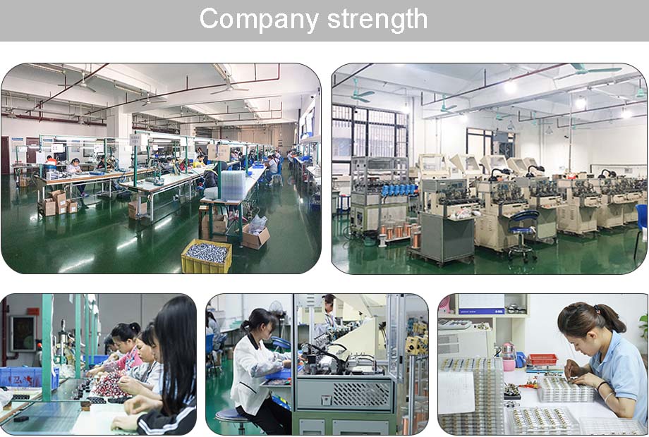
when it come to volume production,we're a major player as well .each month,we rurn out 600000 units,all of which are compliant with the rohs directive.Have any questions or special needed, please contact us, we have the engineer group and best sales department to service to you
Looking forward to your inquiry. Welcome to our factory.

Door Lock Motor
Door Lock Motor,Mini Door Lock Motor,Door Lock Dc Motor,Door Lock Gear Motor
Shenzhen Shunchang Motor Co., LTD. , https://www.scgearmotor.com