Abstract: The control board of the vehicle display control system uses a high-performance PowerPC MPC8548E processor to expand the display, memory, flash memory and interface devices. With this motherboard as the platform, real-time display and control of vehicle data and video is realized. This article focuses on the implementation of I2C control in software on PowerPC and the method of communication between devices through the PCI bus.
This article refers to the address: http://
The vehicle display control system is a system for displaying and controlling the vehicle working state information and completing human-computer interaction. The vehicle display control system needs to respond to key operations while displaying text, graphics and video, and to control the vehicle control system. This requires the system to have the ability to respond in real time and process multiple tasks in parallel. In this paper, the real-time operating system VxWorks is applied to the control board with PowerPC MPC8548E as the processor, which realizes the function of real-time response to system operation and display of corresponding information. This motherboard is the core control system of the main control system, with high performance, high stability and good compatibility.
1 PowerPC MPC8548 and its control board overview
The PowerPC MPC8548 is a high-performance processor from the new generation PowerQUICC III family developed by Freescale. It has an internal operating frequency of 1.33 GHz and can handle up to 3 065 MIPS at this operating frequency. The L1 cache has 32 KB of instruction cache and data cache, 512 KB of L2 cache, supports DDR1 and DDR2 memory controllers, supports PCI, PCI-X and PCIE interfaces, supports SRapid IO interface and 4 GbE interfaces. MPC8548 not only has powerful data processing capabilities, but also has strong communication processing capability, high reliability, and good resistance to harsh environments. It is especially suitable for occasions with high network performance requirements and multiple interfaces.
The core control board of the vehicle display control system is an embedded system with PowerPCMPC8548E as the processor. The system constitutes a high-performance, high-reliability core control board by extending the display, memory, flash memory and other interface control circuits. In this way, the motherboard is controlled as a hardware platform, the embedded real-time operating system VxWorks is transplanted, and the interface device driver is redeveloped. Then VxWorks is used as a software development platform to develop an application program to realize display and control tasks.
2 PowerPC control board hardware design
As shown in Figure 1, the PowerPC control board hardware system consists of a processor, peripheral circuits, and external interface devices. The peripheral circuit includes Power Supply, crystal oscillator and reset circuit; the external interface circuit includes serial port, network port, EL/LVDS liquid crystal display, 16-bit PCI bus, USB interface, Flash, Mouse and Keyboard.
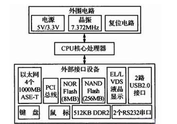
PowerPC control board hardware structure diagram
3 PowerPC control board software design
The vehicle display control system is a multi-tasking complex real-time embedded system that uses the operating system to allocate, schedule, control and coordinate all hardware and software resources, especially to coordinate concurrent activities such as task scheduling, memory management, synchronization mechanism, and exceptions. Interrupt processing, inter-task communication, etc. VxWorks from WindRiver (now acquired by Intel) is a real-time embedded operating system. The VxWorks operating system has been widely used in aerospace, automotive and other industries. Given VxWorks' support for the PowerPC processor architecture, embedded systems using PowerPC processors are mostly used as operating systems. Therefore, the vehicle display control system also uses VxWorks as the operating system.
The embedded system is a system that configures and reduces hardware resources according to actual requirements. Since the embedded product is a combination of software and hardware, and with the development of the product, the software has been solidified in the hardware environment. Therefore, the comprehensive development of software and hardware is a major feature of the embedded system, and the software design is closely linked. Completed on the basis of hardware.
The software design of the PowerPC control board follows the architectural design method of the embedded software and is divided into the following two parts:
1 Development of special device drivers, integration of general device drivers, ie development of board support package BSP.
2 application development, that is, the realization of the display control task.
3.1 Device Driver Development
Since the hardware platform of the system is designed according to actual needs, the device driver must be developed according to the actual interface. In the general device-driven architecture provided by VxWorks, combined with the working principle and function of each specific device, the data flow is centered, and after the communication mode between the device and the CPU and the external device is mastered, the driving of the specific device is developed one by one. After the device driver development is completed, the board support package BSP of the MPC8548E is finally formed. The integration of hardware device programs includes the following aspects.
(1) Special equipment drive
Drivers for some special devices are not included in the list of standard devices that VxWorks is equipped with, so you need to develop them yourself, such as PCI line drivers, DDR memory drivers, and display drivers.
(2) Universal device driver
Drivers for general-purpose devices can be directly applied to VxWorks standard drivers, or can be slightly modified based on standard drivers, such as mouse, keyboard, serial port, Ethernet interface and USB interface.
3.2 Application Development
Firstly, the tasks to be completed by the vehicle display control system are decomposed into multiple tasks: button query, interface switching, data display, video display and parameter storage. The application ensures that tasks are completed in real time in the prescribed manner. PowerPC control board software structure diagram shown in Figure 2.
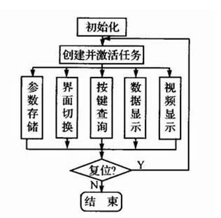
PowerPC control board software structure diagram
Key query: Timed query whether there is a key press, if any, send a message to the interface switch, data display, video display and parameter storage to complete the corresponding task.
Interface switching: Switch to the corresponding interface.
Data display: Shows the status of the vehicle control system in different operating modes.
Video display: Switch the video channel, adjust the brightness and contrast of the image, and perform related operations.
Parameter storage: Save parameters according to instructions, or save parameters to the cache at equal intervals.
3.2.1 Software Implementation of I2C Interface Control
The I2C bus is a two-wire serial bus that is mainly used for the expansion of microprocessor peripheral chips. It requires only two wires—the serial data line and the serial clock line—to perform data exchange between the microprocessor and the device with the I2C bus interface on the bus.
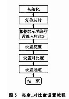
I2C bus devices are widely used for their simplicity and effectiveness. The video decoder CCX25836 for analog video display in the vehicle display control system is one of them. The registers of CCX25836 need to be configured with I2C bus. The system design uses FPGA to build the hardware I2C electrical structure. On the PowerPC control board, the software simulates the I2C read and write process required by the video decoder, and sets its registers to realize the video channel switching. Video display function such as adjustment of brightness and contrast. The I2C read and write process is shown in Figure 3 and Figure 4. The process of setting the brightness and contrast through the I2C bus is shown in Figure 5.
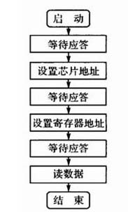
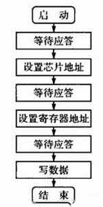
I2C read and write process
3.2.2 Inter-device communication via PCI local bus
The PCI local bus is the interconnection interface between the processor/memory and the peripheral control unit and the expansion card in the microcomputer. The PCI local bus specification is the protocol of the interconnection mechanism and the specification of the electrical and mechanical configuration. The PCI local bus has bus master support and auto-configuration capabilities, providing three types of address space, namely memory, I/O, and configuration address space. These features lay the foundation for communication between devices on the bus.
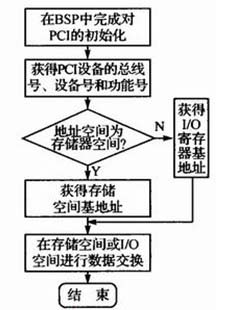
There are multiple PCI devices in the vehicle display and control system. In view of the strong processing power of PowerPC and the real-time multi-tasking function of the real-time operating system, the PowerPC control board becomes the “master device†and is responsible for the coordination between devices. equipment". The "master device" configures the device identification number and the vendor identification number of the "slave device", and performs data communication according to the storage mapping access mode of the address space. The communication process between PCI devices is shown in Figure 6.
3.3 Application and device driver connection
The application accesses the device by calling a device driver. There are three ways to call a device driver: direct call, call through the operating system kernel, and call through the operating system's extension module. The direct invocation method enables the application to access the device efficiently, but the portability is poor, and the user needs to manage the device by himself; the kernel is called by the operating system, the portability is good, but the system overhead is increased; the advantages and disadvantages of the module call by the extension module are Similar through the kernel call.
The vehicle display control system is a complex real-time operating system that requires good portability and an extension module. Therefore, the application uses both the kernel and the extension module to call the device driver. A special device driver is called through the kernel, and a special driver is called through the extension module.
3.4 Direct connection between application and device
For the control requirements of some special devices, the PowerPC control board adopts direct control mode instead of device driver.
The I2C bus is a two-wire serial bus that is mainly used for the expansion of microprocessor peripheral chips. It requires only two wires—the serial data line and the serial clock line—to perform data exchange between the microprocessor and the device with the I2C bus interface on the bus.
I2C bus devices are widely used for their simplicity and effectiveness. The video decoder CCX25836 for analog video display in the vehicle display control system is one of them. The CCX25836 registers need to be configured with the I2C bus. The system design uses FPGA to build the hardware I2C electrical structure. On the PowerPC control board, the software simulates the I2C read and write process required by the video decoder (see Figures 3 to 4). Registers, thus enabling video display functions such as switching of video channels and adjustment of brightness contrast, as shown in Figure 5.
Conclusion
The PowerPC MPC8548E microprocessor is favored by embedded system developers for its rich interface, strong computing power, fast processing speed, stability and scalability. The motherboard of the vehicle display control system uses this chip as the core processor, equipped with the necessary peripheral interfaces, and uses VxWorks as the operating system running on it, so that it has the ability to handle multitasking in real time. By extending the PCI device, data exchange and control between the display control system devices, the display system and other system devices are realized.
4 in 1 magsafe wireless charging
Guangzhou Lufeng Electronic Technology Co. , Ltd. , https://www.lufengelectronics.com