As a precision instrument, laser treatment machine requires precise control and strict requirements on dustproof, antistatic, and moistureproof. The input device of the laser therapy machine is controlled by a touch screen, which is based on the above requirements and is considered from the perspective of user convenience and intuitive interface. The application of the touch screen integrates the display of data and the input of data, simplifying the entire device.
1 Principle of touch screen
The touch screen is attached to the surface of the display and is used in conjunction with the display. An analog electrical signal is generated through touch, and the coordinates of the touched point are calculated by a microprocessor after being converted into a digital signal, so as to obtain the operator's intention and execute it. Touch screens can be divided into five categories according to their technical principles: vector pressure sensing, resistive, capacitive, infrared, and surface acoustic wave. Among them, resistive touch screens are often used in practical applications. The resistive touch screen is composed of 4 layers of transparent thin, the bottom is a base layer made of glass or plexiglass, and the top is a plastic layer with a hardened outer surface that is smooth and scratch-resistant. It is a metal conductive layer (OTI, indium oxide). These two layers are insulated by small transparent isolation points. When a finger touches the screen, the two conductive layers are in contact at the touch point.
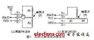
The two metal conductive layers of the touch screen are used to measure the coordinates of the X-axis and Y-axis directions, respectively. The conductive layer used for X coordinate measurement leads two electrodes from the left and right ends, denoted as X + and X-. The conductive layer used for Y coordinate measurement leads two electrodes from the upper and lower ends, denoted as Y + and Y-. This is the lead structure of the four-wire resistive touch screen. When a voltage is applied to a pair of electrodes, a uniform and continuous voltage distribution is formed on the conductive layer. If a certain voltage is applied to the electrode pair in the X direction and no voltage is applied to the electrode pair in the Y direction, in the X parallel voltage field, the voltage value at the contact point can be reflected on the Y + (or Y-) electrode By measuring the voltage of the Y + electrode to ground, the X coordinate value of the contact can be known. Similarly, when voltage is applied to the Y electrode pair and no voltage is applied to the X electrode pair, the Y coordinate of the contact point can be obtained by measuring the voltage of the X + electrode. The measurement principle is shown in Figure 1.

The five-wire touch screen is different from the four-wire type. The main difference is that the five-wire touch screen uses the four terminals of one of the conductive layers as four electrodes, and the other conductive layer only outputs the voltage in the X and Y directions as the measured conductor. The X and Y directions are alternately used during measurement Apply voltage.
2 Working principle of touch screen controller
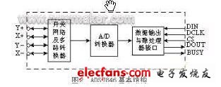
There are many kinds of touch screen controllers. The main functions are to apply voltage to the two directions of the touch screen under the control of the microprocessor, and send the corresponding voltage signal to its own A / D converter. The digital signal is read into the microprocessor under the action of the synchronous clock provided by the port. The basic structure of the controller ADS7846 is shown in Figure 2.

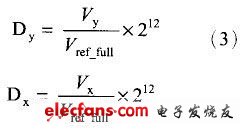
Figure 1 The measurement result at the touch point P is calculated as follows:

The resolution of the A / D converter can be set to 8 bits or 12 bits in the ADS7846 through the setting of registers. In this system, the resolution of the A / D converter is 12 bits. Then the binary output code of point P is:

Among them: It is the reference voltage that is added to ADS7846 internal A / D converter.
The operation of the touch screen controller is controlled through the serial data input port DIN input control command.

bit7 indicates the start of sending command, high level is effective. A2: A0 is used to select the data input channel, 101 selects X coordinate measurement, 001 selects Y coordinate measurement. MODE defines the resolution of the internal analog-to-digital converter as 8 bits (MODE = 1) or 12 bits (MODE = 0). SER / DFR is the single-ended / double-ended reference voltage selection bit. PD1: PD0 can be selected and set according to the need of power saving mode. The setting of these command control bits will be applied in the program code part.
3 System hardware design
The input system of the laser treatment machine is composed of three parts: touch screen, touch screen controller and microcontroller. The microcontroller uses Microchip's new chip PIC16F876. The internal bus adopts Harvard dual bus structure. In the case of the same internal frequency, the data transmission speed is accelerated, and the bottleneck phenomenon is avoided. This chip uses a reduced instruction set (RISC) that is easy to use and speeds up development. It contains 8KB of program memory (page operation), 256 bytes of EEPROM, 368 bytes of RAM, 8 analog-to-digital converters, 1 universal serial port (SCI), 1 I2C interface, and 1 serial peripheral interface (SPI ), 3 timers and watchdog circuits (WathcDog) and many other important resources. The multiplexing of many peripheral interface functions makes the entire microcontroller simple and powerful.
According to the interface characteristics of data exchange between ADS7846 and microcontroller, the SPI port of PIC16F876 is selected. The SPI port includes three signals: SDO (serial data output), SDI (serial data input), and SCK (serial synchronous clock). The hardware connection relationship is shown in Figure 3.
This article focuses on the design of the input system of the laser therapy device, and the design of other hardware only gives the meaning of the interface. Due to the high degree of internal integration of the PIC16F876, the peripheral interface is quite simple, but the internal registers must be set to complete complex control functions.
Midi Fuse Block,Midi Fuse Box,Bussmann Midi Fuse Holder,Victron Midi Fuse Holder
Dongguan Andu Electronic Co., Ltd. , https://www.idofuseholder.com