As the car changes from a transit tool to a personalized consumer product that combines leisure and entertainment, consumers' demands for car entertainment continue to increase, and the automotive industry is facing strong market pressure, which needs to be reduced without sacrificing performance. Cost, this phenomenon is particularly evident in the entry-level automotive market, and consumer demand for low-cost vehicles has allowed the low-end media entertainment market to grow at an annual rate of more than 10%. AM/FM radios are especially popular for their low cost and high sound quality. How to design a broadcast audio product that meets both cost control requirements and high-quality audio enjoyment to meet the demand for cost reduction and simple design in this field has become the focus of the industry. We can imagine the continuous improvement and continuous innovation of the radio, making the development of the radio more and more.
This article refers to the address: http://
How to design a broadcast audio product that meets both cost control requirements and high-quality audio enjoyment to meet the demand for cost reduction and simple design in this field has become the focus of the industry. In order to realize low-cost AM/FM car radio application, this paper introduces low-cost microcontroller MC9S08QG8, integrated radio chip TEF6621, low-cost audio processing and high-fidelity power output scheme, and reduces the hardware design circuit, while describing the device selection and overall Build ideas and hardware design details. This design can meet the requirements of low power consumption, low cost, high performance and high sound quality.
The specific design of the hardware circuit
According to the previous device selection and overall construction considerations, the specific design circuit of the AM/FM car radio completed in this paper is shown in Fig. 4. Most of the pins of the MC9S08QG8 microcontroller (MCU) have multiple functions. In the circuit design, the MC9S08QG8 is used as the control core to realize various control such as display, tuning, audio sound, and power amplifier output.
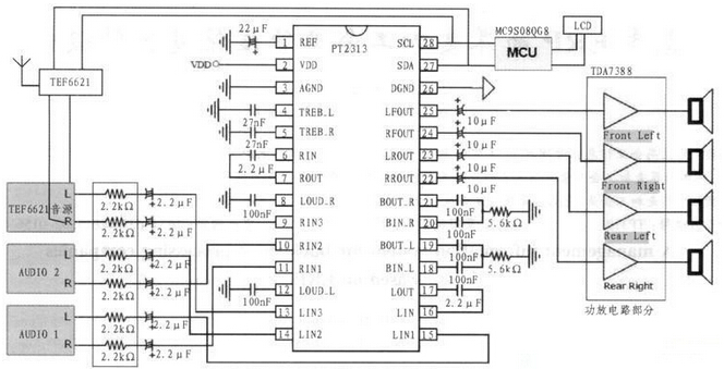
AM/FM car radio hardware block diagram
The schematic diagram of the AM/FM car radio application here is divided into three parts. The first part is the basic connection required for the MC9S08QG8 MCU. The second part is the TEF6621 tuner and antenna receiving circuit, the third part is the audio processing and power amplifying output circuit composed of PT2313 and TDA7388, and the fourth part is the human-computer interaction circuit of 16x2 LCD and code potentiometer.
The standard voltage of the car battery is 12/24 V. In this design, the DC-DC voltage adjustment circuit is used to output 1 channel 9 V voltage and 1 channel 5 V voltage. The microcontroller, display part and other low voltage peripheral parts are powered by 5 V. The digital voltage, the tuner TEF6621 and the audio chip PT2313 are powered by 9 V, and the power amplifier TDA7388 is powered by the car battery. The clock circuit of the MCU does not need an external crystal oscillator, and directly uses the clock that is built in the MCU. The TEF6621 tuner, PT2313, TDA7388 and its peripheral circuits use the minimum hardware requirements for the work provided in the data sheet. The connection between the MCU and the TEF6621 tuner and PT2313 is connected according to the standard IIC mode. The MCU is the master, and the TEF6621 and PT2313 are the slaves. The SDA and SCL signal lines are basically configured and operated on the two devices through different slave addresses to realize tuning. With tuning function. MCU's 8K FLASH and 512 bytes of memory resources are sufficient for basic radio control. In addition, if further expansion of functions is required on the basis of this system, the on-chip resources are tight, and Freescale also provides pin-to-pin compatibility. Low-cost upgrade solution such as MC908QG16/32.
Analysis of the principle of RS232 serial port to infrared communication circuit
As a means of data transmission, infrared communication can be applied in many occasions, such as infrared remote control of home appliances, entertainment facilities, automatic meter reading of water, electricity and gas energy consumption measurement. Especially in the electronic power industry, there are more and more products using infrared technology for communication. People can use infrared technology to make short-distance copy control of products, which is very simple and convenient. The serial port is a very common device communication protocol on a computer. Most computers include an RS 232-based serial port. The concept of serial communication is very simple. The serial port sends and receives bytes in bits. The communication described in this article is done using 3 lines: ground; send; receive. Since serial communication is asynchronous, a port can send data on one line while receiving data on another line.
Level conversion
Since the level of the RS 232 signal is inconsistent with the level of the serial port signal of the microcontroller, level conversion between the two must be performed. The MAX232 is commonly used to implement RS232/TTL level conversion. The MAX232 internal structure has three parts:
(1) Charge pump circuit. It consists of 1~6 pins and 4 capacitors. (2) Data conversion channel. Two data channels are composed of 7~14 pins. RS 232 data is converted from R1in, R2in input to TTL/COMS data and output from R1out, R2out; TTL/COMS data is converted from T1in, T2in input to RS 232 data from T1out, T2out to computer DB9 port. (3) External power supply circuit. External power supply is the use of computer USB output +5 V power supply effective power supply, not only saves the design of the circuit, and saves volume in actual production, the circuit principle is shown in Figure 1.
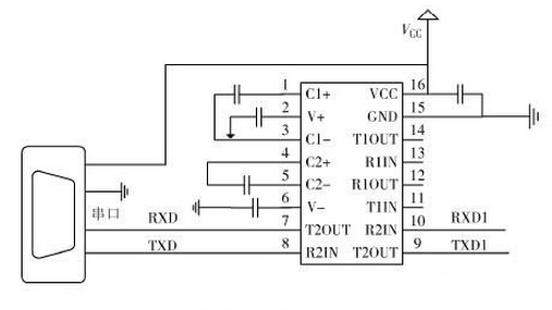
Figure 1 circuit schematic
Infrared emitting part
When the infrared transmitting end transmits data, the binary data to be transmitted is modulated into a series of burst signals and transmitted, and the infrared carrier is a square wave with a frequency of 38 kHz. The infrared carrier can be realized by the PWM function of the internal timer of the microcontroller, or it can be realized by the peripheral hardware circuit. Here, the 38 kHz crystal oscillator is used to generate a stable oscillation signal, and the CD4069 non-gate circuit is used to realize the square wave oscillation signal through a series of conversions. The level-converted COMS data signals are superimposed to drive the triode conduction, thereby realizing the TSAL6200 infrared emission diode to convert the periodic electrical signal into a certain frequency of infrared light signal, as shown in Figure 2.
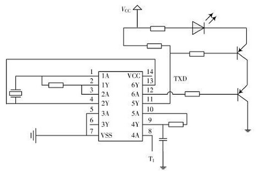
Figure 2 shows the infrared emission end
Infrared receiving part
The infrared receiver adopts the HS0038B infrared receiver. The principle of the infrared receiving circuit is: when receiving the carrier signal of 38 kHz, the HS0038B receiver will output a low level, otherwise it will output a high level, so that the infrared light signal can be demodulated into a certain period. The continuous square wave signal can be recovered by the single chip microcomputer to recover the original data signal. HS0038B is a miniaturized receiving device capable of receiving infrared signals. Its epoxy package can be used as an infrared filter, so there is no need to add an infrared filter. The biggest advantage is that the output is also very stable in highly disturbing environments. The circuit design is shown in Figure 3. In this paper, the CD4093 logic NAND gate chip and HS0038B receiver are used to build the circuit output data. At the same time, the other level of the chip pins are used to self-lock the conversion level data of the MAX232 output to avoid the signal self-receiving. .

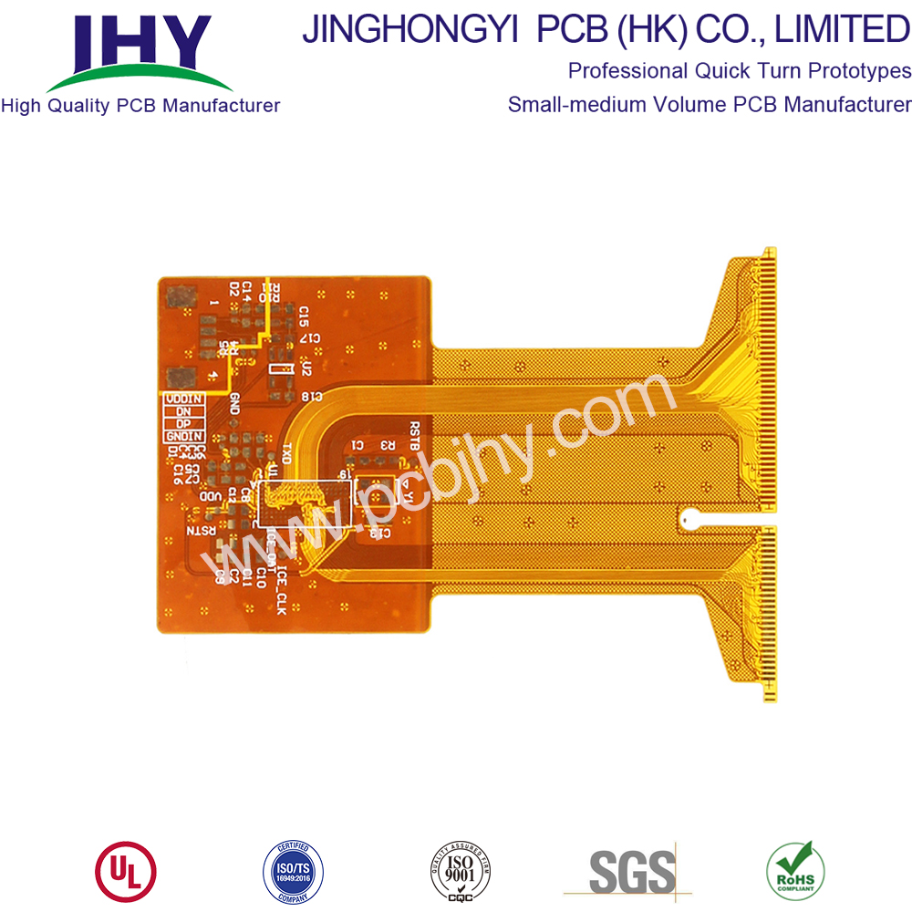
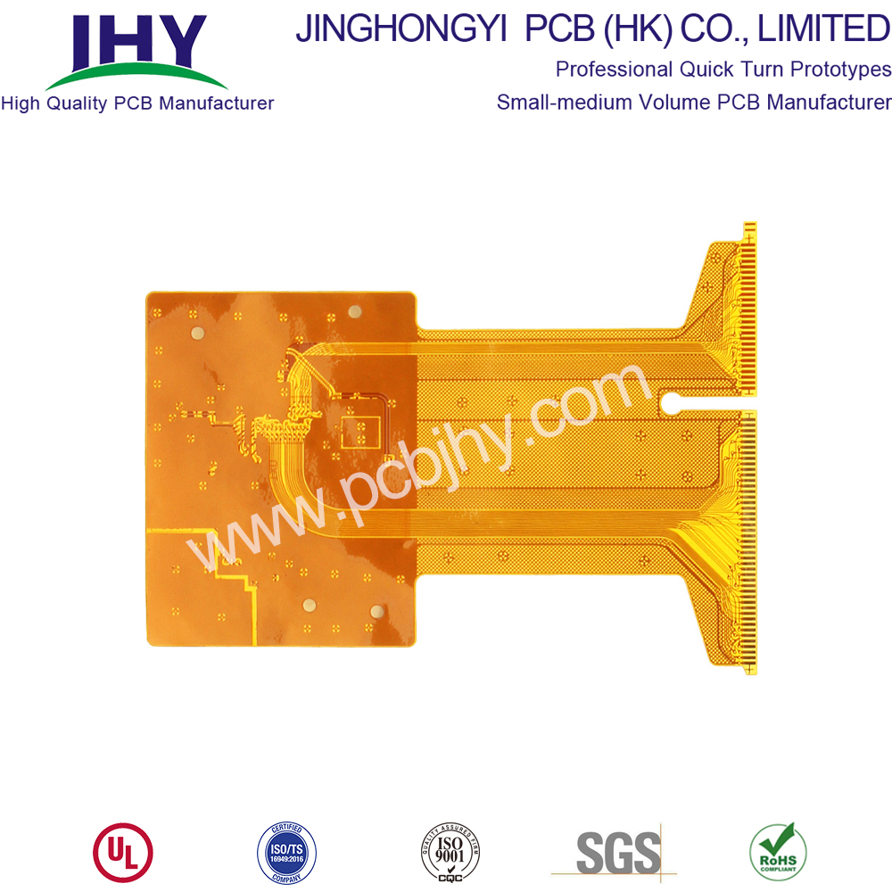
Flexible PCB , allowing the board to conform to a desired shape, or to flex during its use.
If you need a manufacturer who can manufacture flexible PCB for you, you should make it clear that this PCB manufacturer should have a mature and current process flow for manufacturing flexible circuit board. Considering factors such as manufacturing cost, we suggest that you choose a Chinese PCB manufacturer. Because, at present, PCB Manufacturing industry is basically concentrated in China. It is not only because China's manufacturing industry is very developed, but also because it has a very mature production process and can effectively reduce the cost of manufacturing products for you.
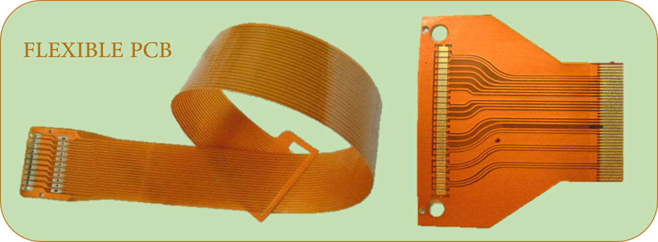
WHAT IS FLEXIBLE PCB?
Flexible PCB, also known as Flexible electronics, flexible circuit board, Flex PCB , flex circuits, is a technology for assembling electronic circuits by mounting electronic devices on flexible plastic substrates, such as polyimide, PEEK or transparent conductive polyester film. Additionally, flex circuits can be screen printed silver circuits on polyester. Flexible electronic assemblies may be manufactured using identical components used for rigid printed circuit boards, allowing the board to conform to a desired shape, or to flex during its use. An alternative approach to flexible electronics suggests various etching techniques to thin down the traditional silicon substrate to few tens of micrometers to gain reasonable flexibility, referred to as flexible silicon (~ 5 mm bending radius).
Flexible circuit boards are widely used in automobiles, medical, telecommunications, industry or commerce.
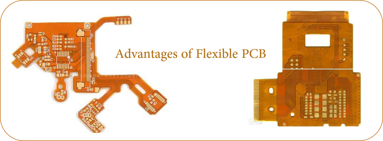
What are Advantages of Flexible PCB?
Flexible PCB is essentially different from Rigid PCB . Although rigid PCB is currently the most produced PCB in the world, the use of flexible PCB has many advantages, including:
- Save space and weight. Flexible PCB design requires only about 10% of the space and weight of common PCB components to provide greater freedom of installation and packaging. The inherent flexibility also allows for more compact flexibility. Because of its lighter weight, it also reduces transportation costs.
- Increased stability and reliability. A Flexible Printed Circuit Board requires fewer interconnects, which in turn requires fewer contact crimps, connectors and solder joints. Simply put, a flexible PCB Board does not contain as many potential sources for failure, which enhances their reliability.
- Compatibility and other superior performance. Flexible Printed Circuit boards can be compatible with almost any type of connectors or components, and can be used with ZIP connectors and other components, so the compatibility of flexible Printed Circuit Boards is incomparable with other PCBs. They also perform well at extreme temperatures and exhibit excellent radiation and chemical resistance.
- Effective Cost Control. Cost-saving advantages of flexible PCB include reducing material and packaging requirements, reducing component replacement costs and possibly leading to assembly errors requiring maintenance.
- Reduced wiring errors
- Elimination of mechanical connectors
- Unparalleled design flexibility
- Higher circuit density
- More robust operating temperature range
- Stronger signal quality
- Improved reliability and impedance control
These benefits make flex PCBs ideally fit for a wide range of applications in industries such as Military, Transportation, Medical, Consumer Electronics, Automotive, Aerospace, Communications and Industrial.
Flex PCB disadvantages also exist:
- Material costs are higher than rigid or Rigid Flex PCB , and overall manufacturing costs are higher.
- At low temperature, the performance of flexible circuit boards can not be compared with other PCBs.
- Making the assembly process more difficult and complex
- Easily damaged through improper handling (easy to bend and dent)
- If scratch occurs, it is easy to damage.
- Difficult or impossible to repair once damaged
- Storage conditions are more stringent than general circuit boards. Sulfur-free plastic packaging should be considered.
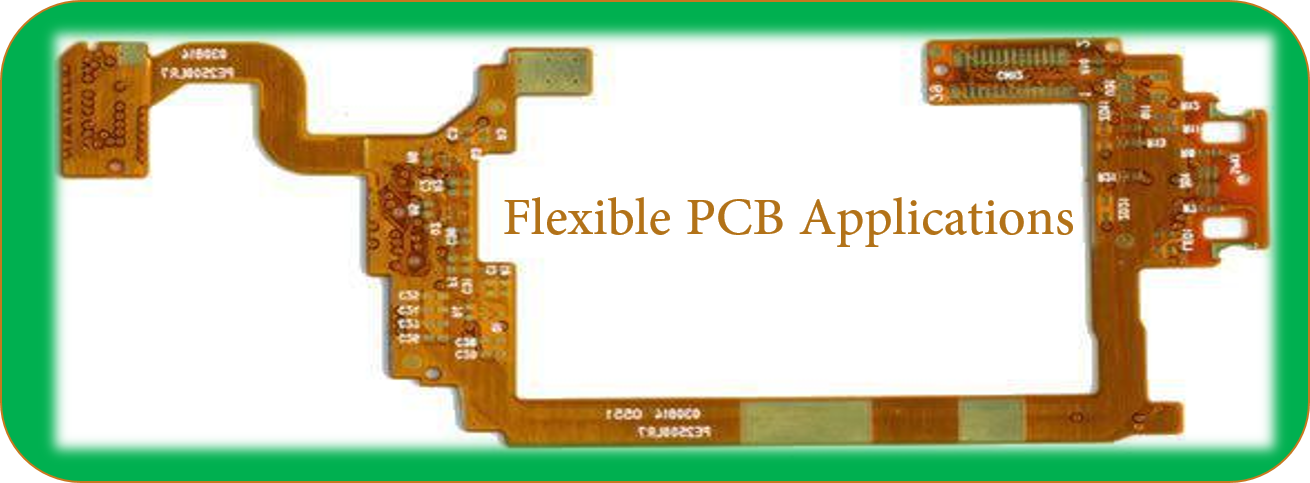
Flexible PCB Applications
- Flexible Circuits are usually used as connectors in various applications, because they have incomparable flexibility, save space and are easier to maintain than rigid circuit boards in the later period. Flexible circuits are commonly used in computer keyboards; most keyboards use flexible circuits as switching matrices.
- Glass is used as a substrate in LCD manufacturing. If a thin flexible plastic or metal foil is used as the substrate, the whole system can be flexible, because the film deposited on the top of the substrate is usually very thin, about a few microns.
- Organic light-emitting diodes (OLED) are usually used instead of backlights for flexible displays, thus making flexible organic light-emitting diode displays.
- Most flexible circuits are passive wiring structures that are used to interconnect electronic components such as integrated circuits, resistors, capacitors and the like; however, some are used only for making interconnections between other electronic assemblies either directly or by means of connectors.
- In the automotive field, flexible circuit boards are used for dashboards, under-hood control devices, circuits hidden in cab roofs, and ABS systems. In computer peripherals, a flexible PCB is used on the printer's mobile print head and the signal is connected to the mobile arm carrying the read/write head of the disk drive. Consumer electronic devices use flexible circuits in cameras, personal entertainment devices, calculators or motion monitors.
- Flexible circuits are found in industrial and medical devices where many interconnections are required in a compact package. Cellular telephones are another widespread example of flexible circuits.
- Flexible solar cells have been developed for powering satellites. These cells are lightweight, can be rolled up for launch, and are easily deployable, making them a good match for the application. They can also be sewn into backpacks or outerwear.
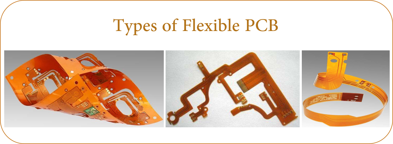
Types of Flexible PCB
There are a few basic constructions of flexible circuits but there is significant variation between the different types in terms of their construction. Following is a review of the most common types of flexible circuit constructions
-
Single sided Flexible PCB
Single-sided flexible circuits have a single conductor layer made of either a metal or conductive (metal filled) polymer on a flexible dielectric film. Component termination features are accessible only from one side. Holes may be formed in the base film to allow component leads to pass through for interconnection, normally by soldering. Single sided flex circuits can be fabricated with or without such protective coatings as cover layers or cover coats, however the use of a protective coating over circuits is the most common practice. The development of surface mounted devices on sputtered conductive films has enabled the production of transparent LED Films, which is used in LED Glass but also in flexible automotive lighting composites.
-
Double access or back bared Flexible PCB
Double access flex, also known as back bared flex, are flexible circuits having a single conductor layer but which is processed so as to allow access to selected features of the conductor pattern from both sides. While this type of circuit has certain benefits, the specialized processing requirements for accessing the features limits its use.
-
Sculptured Flexible PCB
Sculptured flex circuits are a novel subset of normal flexible circuit structures. The manufacturing process involves a special flex circuit multi-step etching method which yields a flexible circuit having finished copper conductors wherein the thickness of the conductor differs at various places along their length. (i.e., the conductors are thin in flexible areas and thick at interconnection points.).
-
Double sided Flexible PCB
Double-sided flex circuits are flex circuits having two conductor layers. These flex circuits can be fabricated with or without plated through holes, though the plated through hole variation is much more common. When constructed without plated through holes and connection features are accessed from one side only, the circuit is defined as a "Type V (5)" according to military specifications. It is not a common practice but it is an option. Because of the plated through hole, terminations for electronic components are provided for on both sides of the circuit, thus allowing components to be placed on either side. Depending on design requirements, double-sided flex circuits can be fabricated with protective coverlayers on one, both or neither side of the completed circuit but are most commonly produced with the protective layer on both sides. One major advantage of this type of substrate is that it allows crossover connections to be made very easy. Many single sided circuits are built on a double sided substrate just because they have one of two crossover connections. An example of this use is the circuit connecting a mousepad to the motherboard of a laptop. All connections on that circuit are located on only one side of the substrate, except a very small crossover connection which uses the second side of the substrate.
-
Multilayer Flexible PCB
Flex circuits having three or more layers of conductors are known as multilayer flex circuits. Commonly the layers are interconnected by means of plated through holes, though this is not a requirement of the definition for it is possible to provide openings to access lower circuit level features. The layers of the multilayer flex circuit may or may not be continuously laminated together throughout the construction with the obvious exception of the areas occupied by plated through-holes. The practice of discontinuous lamination is common in cases where maximum flexibility is required. This is accomplished by leaving unbonded the areas where flexing or bending is to occur.
-
Rigid flex PCB
Rigid flex PCB circuits are a hybrid construction flex circuit consisting of rigid and flexible substrates which are laminated together into a single structure. Rigid-flex circuits should not be confused with rigidized flex constructions, which are simply flex circuits to which a stiffener is attached to support the weight of the electronic components locally. A rigidized or stiffened flex circuit can have one or more conductor layers. Thus while the two terms may sound similar, they represent products that are quite different.The layers of a rigid flex are also normally electrically interconnected by means of plated through holes. Over the years, rigid-flex circuits have enjoyed tremendous popularity among military product designer, however the technology has found increased use in commercial products. While often considered a specialty product for low volume applications because of the challenges, an impressive effort to use the technology was made by Compaq computer in the production of boards for a laptop computer in the 1990s. While the computer's main rigid-flex PCBA did not flex during use, subsequent designs by Compaq utilized rigid-flex circuits for the hinged display cable, passing 10s of 1000s of flexures during testing. By 2013, the use of rigid-flex circuits in consumer laptop computers is now common.
Rigid flex PCB board are normally multilayer structures; however, two metal layer constructions are sometimes used.
-
Polymer thick film flexible PCB
Polymer thick film (PTF) flex circuits are true printed circuits in that the conductors are actually printed onto a polymer base film. They are typically single conductor layer structures, however two or more metal layers can be printed sequentially with insulating layers printed between printed conductor layers, or on both sides. While lower in conductor conductivity and thus not suitable for all applications, PTF circuits have successfully served in a wide range of low-power applications at slightly higher voltages. Keyboards are a common application, however, there are a wide range of potential applications for this cost-effective approach to flex circuit manufacture.
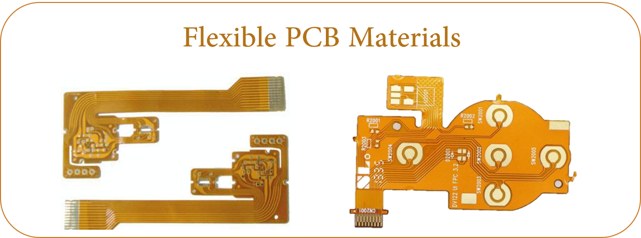
Flexible PCB materials
Each element of the flex circuit construction must be able to consistently meet the demands placed upon it for the life of the product. In addition, the material must work reliably in concert with the other elements of the flexible circuit construction to assure ease of manufacture and reliability. Following are brief descriptions of the basic elements of flex circuit construction and their functions.
- Base material
- Bonding adhesive
- Metal foil
In certain non standard cases, the circuit manufacturer may be called upon to create a specialty laminate by using a specified alternative metal foil, such as a special copper alloy or other metal foil in the construction. This is accomplished by laminating the foil to a base film with or without an adhesive depending on the nature and properties of the base film.
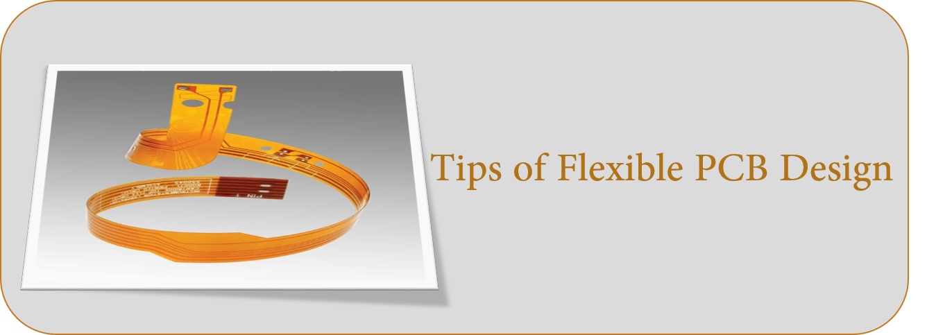
Tips of flexible PCB design
The shortest distance between two points is a straight line, so a circuit trace is a circuit trace on a flexcircuit will look like a circuit trace on a Rigid Circuit Board , right? Actually there can be considerable differences between designing a rigid PCB and a flexible PCB. Because of the flexibility feature, there are unique issues affecting robustness. For example, since flex can bend, one needs to be sure that bending does not crack or break solders joints near a bend location. For this reason, design features like radiused corners and filleted pads are common on flexible circuits. Another issue is the substrate used for flex is not as dimensionally stable vs. the hardboard cousin. Allowances for dimensional changes may be required for flexible PCB design. Most PCB design software is tailored to rigid printed circuit materials and features. Tradeoffs occur when this same software is used to design flexible PCB's.
tools
Both PCBs and flexible PCBs use similar tooling such as CAD files, photo tools and electrical test fixtures. Perhaps the biggest difference is around the cutline definition. Flexible circuits provide unlimited configuration opportunities that often results in very odd shapes and sizes. Circuit boards often are rectangular or may have some notches or curved outlines routered. Because of this nuance, steel rule dies and hard tool dies are probably used more often for flexible PCBs than for boards, at least for ultra high volume applications. Laser definition of the circuit outline is also a common flexcircuit process. Other differences in tooling involve fixturing that may be required to handle flexible substrates.
JHYPCB: A Leading Flexible PCB Manufacturer from China
At JHYPCB, we specialize in the fabrication and assembly of flexible PCB products for use in the manufacturing of medical devices and various types of telecommunication and industrial equipment. Our Custom PCB manufacturing capabilities allow us to develop and produce a top-performing flex PCB that meets your unique requirements. We can also work with you to produce a custom flex PCB Prototype that will significantly improve your prospects of a successful project outcome. For detailed capabilities, please refer to the following form.
| Items | Manufacturing Capability | |
| PCB Layers | 1 - 8layers | |
| Laminate | DuPont PI, Shengyi PI | |
| Maximum PCB Size(Length x Width) | Single Sided PCB | 480*4000mm |
| Double Sided PCB | 480*1800mm | |
| Multilayers | 236*600mm | |
| Minimum Board Thickness | Single Sided PCB | 0.05mm+/-0.02mm |
| Double Sided PCB | 0.08mm+/-0.02mm | |
| Multilayers | As per Gerber | |
| Finished Board Thickness | 1-6L | 0.05mm-0.6mm |
| 8L | 1.6mm | |
| Min Tracing/Spacing | Copper Thickness 1/3 oz: | 0.076mm/0.076mm (1-6L) |
| 0.05mm/0.05mm (8L) | ||
| Copper Thickness 1/2 oz: | 0.076mm/0.076mm (1-6L) | |
| 0.06mm/0.06mm (8L) | ||
| Copper Thickness 1oz: | 0.1mm/0.1mm (1-6L) | |
| 0.065mm/0.065mm (8L) | ||
| Min. Annular Ring | 4mil | |
| Minimum Hole Size | 1-6L | 0.2mm(8mil) (CNC) |
| 8L | 0.15mm(CNC) | |
| Solder Mask Color | Green, White, Blue, Black, Red, Yellow | |
| Solder-stop coating---Coverlay | PI and PET film |
|
| Silkscreen Color | White, Black, Yellow |
|
| Surface Finish | OSP | |
| e HASL | ||
| ENIG(Electroless NickLead-Free Gold) | Ni thickness:2-6um | |
| Au thickness:0.025-0.05um | ||
| Flash Gold | Ni thickness:2-8um | |
| Au thickness:0.025-0.15um | ||
| Immersion Tin | Tin thickness:0.5-1um | |
| PlatingTin | Tin thickness:1-10um | |
| Laser cuPunching | ||
| Special technologies | Peelable solder mask | |
| Gold fingers | ||
| Stiffener (only for PI/FR4 substrate) | ||
| Impedance Control+/-10% | ||
| Rigid Flex PCB | ||
YOU MAY ASK:
-
How are flexible circuits made?
Single-sided flexible circuits have a single conductor layer made of either a metal or conductive (metal filled) polymer on a flexible dielectric film. ... Holes may be formed in the base film to allow component leads to pass through for interconnection, normally by soldering.
-
What is a rigid flex PCB?
Rigid flex printed circuit boards are boards using a combination of flexible and rigid board technologies in an application. Most rigid flex boards consist of multiple layers of flexible circuit substrates attached to one or more rigid boards externally and/or internally, depending upon the design of the application.
-
Who invented flexible electronics?
Paul Eisler
Some historical information about flexible circuitry. Paul Eisler is generally credited as being the inventor of the Printed Circuit Board. Paul Eisler was an Austrian inventor, born in Vienna in 1907. In 1936 Paul Eisler invented the process of using conductive epoxy to create circuit patterns.
-
What is a thin film circuit board?
A thin film circuit board as a set forth in claim 4, wherein the insulator layer comprises a polyimide obtained from biphenyltetracarboxylic dianhydride and phenylenediamine.
-
What is the meaning of flex board?
The flex banner are basically used to shout your messages or product endorsement from the rooftops or the roadsides. ... The flex banner is printed using solvent in and therefore these banners are really cost effective medium of promoting.
Helpful Resources
- Double Sided Flexible PCB
- Flexible PCB Manufacturing Capability
- Flexible PCB and Flex Circuits
- Rigid PCB vs. Flexible PCB:How to choose?
- 8 Layer Flexible PCB Circuit Board manufacturing
- Using aluminium in flexible Circuits Board
Flexible PCB
Flex PCB,Flexible Printed Circuit,Flexi Circuits,Flexible Circuits
JingHongYi PCB (HK) Co., Limited , https://www.pcbjhy.com