China has become one of the largest auto markets in the world, and its important role in the production and life of the national economy has become increasingly prominent. In recent years, research on how to make vehicles more safe, efficient, environmentally friendly and comfortable has attracted more and more attention from researchers in various countries. This information is processed in real time by the associated wireless communication network circuitry. For example, the driver is provided with information such as tips, warnings, and the like of the road. In this way, the driver's driving danger due to fatigue and other factors can be greatly reduced, road traffic and the safety of the driver's body are enhanced. In addition, in the event of a vehicle failure, traffic jam or traffic accident, the vehicle will be dispatched and passengers will travel. bring inconvenience.
With the rapid development of society and the acceleration of commercialization, more and more industries and departments need to grasp real-time information of vehicles or other moving targets and remotely control targets. This kind of demand makes the vehicle data remote transmission control system gradually become a research hotspot at home and abroad. The vehicle data remote transmission control system transmits vehicle information and driving information to the dispatching station in time through the station terminal, and displays the vehicle and road information in real time, which will realize scientific and rational dispatching of vehicles, reduce inconvenience for passengers, and transmit auxiliary driving or avoid accidents. Real-time information, or provide data services such as entertainment information and living information.
1 Design and implementation of vehicle data remote transmission control system
1.1 System overall design
The vehicle remote transmission control system mainly includes two parts: a smart car model and a remote control system.
The smart car model is mainly composed of MC9S12 core control module, road detection module, steering gear steering module, speed detection module and motor drive module. The smart car model identifies the road information through the road detection module, transmits the information to the core control module through the AD conversion information, and then analyzes and processes the core control module, and uses the PID control method to drive the steering gear steering module and the motor, thereby realizing automatic path-finding driving. .
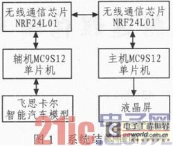
The remote control system consists of two MC9S12 single-chip microcomputers. Remote transmission of vehicle data and control commands is implemented in the middle through the wireless transceiver module NRF24L01. When the system works, the host first sends a command to the slave, and then the slave and the microcontroller on the smart car model use the parallel port communication to communicate the command of the host, and at the same time, the speed, position, servo, motor, etc. of the model car at this time. The parameters are passed back to the host. In this way, the two-way communication between "master to slave, slave to master" is realized in a time period, so that both the data of the smart car and the smart car can be controlled. The block diagram of the remote control system is shown in Figure 1.

1.2 system hardware design
The circuit module of the remote control system mainly includes the MC9S12 single-chip minimum system, power supply module, motor drive module, and NRF14L01 module.
1.2.1 MC9S12 microcontroller minimum system
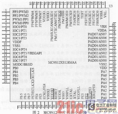
The MC9S12XS128 is only a member of the HCS12X family. The device includes a large number of on-chip processors and external I/O. The MC9S12XS128 is a 16-bit device with 16-bit central processing unit (128KB Flash), 128 kBFlash, 8 kB RAM, and 2 kB EEPROM for on-chip memory. It also includes two asynchronous serial communication interfaces (SCI), two serial peripheral interfaces (SPI), and an 8-channel input capture/output compare (IC/OC) enhanced capture timer (ECT), one 16 Channel 10-bit A/D converter (ADC) and an 8-channel PWM. Figure 2 shows the pinout diagram of the 112 package of the MC9S12XS 128.

Shenzhen Chaoran Technology Corp. , https://www.chaoran-remote.com