Gray code belongs to reliability coding and is an error-mining coding method. Because, although the natural binary code can be directly converted into an analog signal by a digital-to-analog converter, in some cases, for example, when converting from a decimal 3 to 4, each bit of the binary code is changed, so that the digital circuit can be generated very much. Large spike current pulse. Gray code does not have this disadvantage. When it switches between adjacent bits, only one bit changes. It greatly reduces the confusion of logic from one state to the next. Since there is only one bit difference between the two code groups adjacent to this code, in the conversion of the angular displacement amount-digital amount for the direction, the amount of the angular displacement of the direction slightly changes (which may cause the digital quantity to occur). When changing, the Gray code changes only one bit, which is more reliable than the case where other codes change two or more bits at the same time, which reduces the possibility of error.
Gray code is an absolute coding method. The typical Gray code is a one-step self-complement code with reflection characteristics and cycle characteristics. Its cyclic and single-step characteristics eliminate the possibility of significant errors in random access, and its reflection. The self-compensation feature makes reversal very convenient.
Since the Gray code is a variable weight code, each bit code has no fixed size, and it is difficult to directly perform comparison and arithmetic operations, and cannot directly convert into a liquid level signal, and after a code conversion, it becomes a natural binary code. Then read by the host computer.
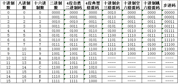
A typical Gray code is a quasi-weight code using absolute coding, and the absolute value of its weight is 2^i-1 (the lowest bit i=1).
The parity of the decimal code of the Gray code is the same as the parity of the number of 1 in the code word.
8421 code turn Gray codeLIBRARY IEEE;
USE IEEE.STD_LOGIC_1164.ALL;
USE IEEE.STD_LOGIC_UNSIGNED.ALL;
USE IEEE.STD_LOGIC_ARITH.ALL;
ENTITY B2G IS
GENERIC(n:INTEGER :=4);
PORT(
Norm : IN STD_LOGIC_VECTOR(n-1 DOWNTO 0);
Grey : OUT STD_LOGIC_VECTOR(n-1 DOWNTO 0)
);
END B2G;
ARCHITECTURE behave OF B2G IS
SIGNAL temp_normal : STD_LOGIC_VECTOR(n-1 DOWNTO 0);
SIGNAL temp_grey : STD_LOGIC_VECTOR(n-1 DOWNTO 0);
BEGIN
PROCESS(norm)
BEGIN
Temp_normal "= norm;
Temp_grey(n-1) <<= temp_normal(n-1)
FOR i IN n-2 DOWNTO 0 LOOP
Temp_grey(i) <<= temp_normal(i+1) xor temp_normal(i);
END LOOP;
Grey "= temp_grey;
END PROCESS;
END behave;
Digital tube display
LIBRARY IEEE;
USE IEEE.STD_LOGIC_1164.ALL;
ENTITY seg7_1 IS
PORT(
A: IN STD_LOGIC_VECTOR(3 DOWNTO 0);
B: OUT STD_LOGIC_VECTOR(6 DOWNTO 0)
);
END seg7_1
ARCHITECTURE seg7_1 _arch OF seg7_1 IS
BEGIN
PROCESS(A)
BEGIN
CASE A IS
WHEN "0000" = "B" = "1111110"; --0
WHEN "0001" = "B" = "0110000"; --1
WHEN "0010" = "B" = "1101101"; --2
WHEN "0011" = "B" = "1111001"; -3
WHEN "0100" = "B" = "0110011"; -4
WHEN "0101" = "B" = "1011011"; -5
WHEN "0110" = "B" = "1011111"; --6
WHEN "0111" = "B" = "1110000"; --7
WHEN "1000" = "B" = "1111111"; --8
WHEN "1001" = "B" = "1111011"; --9
WHEN OTHERS = "B" = "0000000";
END CASE;
END PROCESS;
END;
Four-person majority voter
LIBRARY IEEE;
USE IEEE.STD_LOGIC_1164.ALL;
ENTITY biaojueqi IS
PORT(
A3, A2, A1, A0: IN STD_LOGIC;
Y :OUT STD_LOGIC);
END biaojueqi;
ARCHITECTURE behave OF biaojueqi IS
SIGNAL comb : STD_LOGIC_VECTOR(3 DOWNTO 0);
Signal d: STD_LOGIC_VECTOR(15 DOWNTO 0);
BEGIN
Comb"=A3&A2&A1&A0;
PROCESS(comb)
BEGIN
CASE comb IS
WHEN "0111" = "Y" = '1';
WHEN "1011" = "Y" = '1';
WHEN "1101" = "Y" = '1';
WHEN "1110" = "Y" = '1';
WHEN "1111" = "Y" = '1';
WHEN OTHERS = "Y" = '0';
END CASE;
END PROCESS;
END behave;
Gray code conversion and 8421 code conversion   Design a reversible 4-bit code converter with NAND gate 74LS00 and XOR gate 74LS86. When the control signal C=1, convert 8421 code to Gray code; when C=0, convert Gray code to 8421 code. Write the design steps, list the code transformation relationship truth table and draw the logic diagram, and simulate with multisim
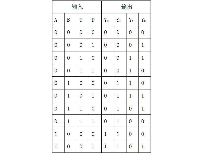
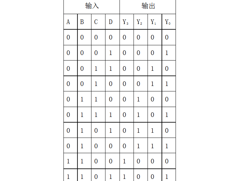
Solution: According to the design method of the combination logic circuit, the input variables are A, B, C, and D, respectively, and the output variables are Y3, Y2, Y1, and Y0; the high level is represented by "1", and the low level is represented by "0". . (1) List truth table
Convert 8421 code to Gray code when C=1
Convert Gray code to 8421 code when C=0
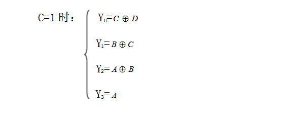
(2) Write a logical function expression and simplify according to the truth table
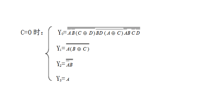
(3) Design a digital logic circuit that implements this logic function according to the simplified logic function expression
Pwm Solar Charger Controller,24V Pwm Solar Charge Controller,Solar Mppt Controller,Power Inverter With Charger
GuangZhou HanFong New Energy Technology Co. , Ltd. , https://www.gzinverter.com