Frequency domain measurements of RF power are the most basic measurements made using spectrum and vector signal analyzers. Such systems must comply with the relevant standards for power transmission and parasitic noise emissions, as well as appropriate measurement techniques to avoid errors. Critical controls on frequency, such as frequency range, center frequency, resolution bandwidth (RBW), and measurement time, all affect measurement results. The frequency range refers to the total spectral component that the analyzer can capture, and the center frequency is equivalent to the center of the frequency range. It should be noted that frequency control such as the frequency range determines the frequency range on the front panel of the instrument. On the other hand, depending on the size of the frequency range, the FFT signal analyzer has two distinct acquisition modes.
The frequency range of up to RBW in the instrument is implemented by downconverting a segment of frequency and then digitizing the downconverted signal. For the frequency range beyond the RBW, the spectrum segments are frequency-converted and digitized in sequence. The RBW controls the frequency resolution on the frequency axis. In traditional analyzers, a narrowband filter is used to scan the frequency range for spectral display. The filter bandwidth determines the resolution on the frequency axis and is therefore a sign of control.
At the same time, the analyzer using FFT does not have an analog filter, but uses FFT and associated windowing parameters to determine the frequency resolution or RBW. Unlike traditional spectrum analyzers, the latest FFT-based analyzers can choose a window to limit spectral leakage and improve resolution in smaller frequency bands in the frequency domain. Those familiar with FFT analyzers and FFTs may ask, what is the relationship between the RBW frequency resolution and the width of the FFT's taps? Table 1 shows the RBW frequency resolution parameters (specified for RBW resolution at 3dB and 6dB) in the new RF signal analyzer versus the FFT tap width.

Table 1: RBW frequency analysis resolution is related to the tap width of the FFT analyzer
The FFT-based analyzer has window selection to limit spectral leakage and improve the resolution of smaller spectra in the frequency domain. Traditional spectrum analyzers do not have this feature. The measurement time (or scan time) of a conventional scanning analyzer is inversely proportional to the square of the RBW, which is determined by the settling time of the analog filter. If the frequency resolution is to be improved by lowering the RBW, the scan time will increase exponentially. Conversely, as RBW decreases, the FFT signal analyzer performs longer acquisitions and more computational effort. As DSP devices speed up, measurements are faster, enabling higher resolution or narrower RBW measurements.

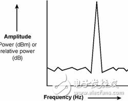
Figure 1: Frequency and amplitude relationship of spectrum analyzer measurements
Amplitude setting
Different amplitude controls can also affect measurement results, including reference levels (reflevel), attenuator settings, and detection modes. The reference level sets the maximum input range of the spectrum analyzer. It controls the Y-axis, which is similar to the "volts/div" on the oscilloscope and must be set to just above the expected maximum power measurement.
The optimum reference level is chosen to minimize instrument distortion (caused by very low reference levels that saturate the input signal) and minimum noise floor (the reference level is too high, reducing the sensitivity and dynamic range of the instrument) Lead to) a balance. Sometimes setting a low reference level is good for wideband noise measurements, albeit with some instrument distortion. When the distortion can be recognized, this will improve the sensitivity of the instrument and ensure that it is excluded from the measurement. The attenuator setting control also determines the input range of the instrument. This setting is usually set to automatic mode and the software adjusts the value of the attenuator based on the reference level.
In firmware, the spectrum analyzer links the Y-axis of the display to a reference level or attenuator. There are no restrictions on virtual instruments, and the Y axis of the display can be separated from these controls if needed. This feature allows for visual scaling of the spectrum without affecting the amplitude settings of the instrument. Note that both the reference level and the attenuator settings affect the programmable attenuator, so just set one of them.
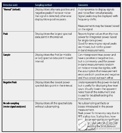
Detection mode is another amplitude control method that can be used with traditional scanning spectrum analyzers, but not for FFT-based analyzers. It can be divided into normal, peak, sampling or negative peak modes. The specific detection mode determines how the spectrum analyzer reduces the spectrum information, or how to compress the spectrum information. It also affects the total power measurement. When the spectral data points exceed the number of points that the spectrum analyzer can display, the analyzer will benefit from the data reduction strategy. This will cause the detection mode to change the power measurement.

Table 2: Factors that the spectrum analyzer measurement mode can affect the accuracy of power measurements
The spectrum analyzer uses a frequency sweep between the start and stop frequencies. An analog ramp signal produces the frequency sweep signal, and the start frequency is synthesized from a time reference signal from high precision. Thus, the measurement accuracy is determined by the analog ramp signal and the center frequency of the IF filter.
FFT-based analyzers do not have such analog ramp signals, so there is no limit to these factors, resulting in consistent accuracy over the entire measurement range. The accuracy within the range depends on the time base and the measurement algorithm, so frequency accuracy and repeatability can be obtained relatively easily.
In conventional scanning analyzers, the causes of frequency errors include reference frequency error, frequency range accuracy (5% of range), and RBW (15% of RBW). Accordingly, the frequency error in the FFT-based analyzer includes the reference frequency error and RBW, depending on the measurement algorithm, ranging from "50%" to "10%" of the RBW.
In order to compare these errors, the reference frequency error must be ignored because a precision frequency source such as a chirped clock can be used to compensate for it. In a swept spectrum analyzer, when the frequency range is greater than 50 kHz and the RBW is set above 1 kHz, the measurement performance will be affected unless an optimized technique is used, such as placing a frequency of 100 MHz to the center of the frequency range.
If a smaller RBW is used, it means that the test time is lengthened because of the scan time problem, because a typical spectrum analyzer requires a scan time of 150-200 ms. The measurement algorithm defines the measurement accuracy of the FFT-based analyzer. For example, the advanced spectral measurement analysis toolkit uses interpolation techniques to achieve higher resolution than RBW can achieve. As in the above example, setting the RBW to 2 kHz will ensure higher accuracy.
FFT-based analyzers use high RBW settings that enable accurate measurements, even without precision-optimized measurement techniques. This means faster and more precise measurements can be achieved in the same test time. The signal analyzer is capable of executing test samples less than 20ms in length, which is six times higher than the spectrum analyzer.
Unless the appropriate measurement setup is used, the measurement results can vary greatly even for the same test instrument. Therefore, a deep understanding of the working principle is crucial for the correct setting of the measuring instrument.
Uv Curving Glass,Tempered Glass Screen Protector,Film Cutting Machine,Uv Curing Protector Screen
Shenzhen TUOLI Electronic Technology Co., Ltd. , https://www.szhydrogelprotector.com