Antennas are an important part of radar, and antenna pattern testing plays an extremely important role in radar performance testing. In the early days, people used the manual method to measure the direction map. The data acquisition, the direction drawing and the parameter calculation were all manual methods, the operation was complicated, the workload was large, the time was long, and the precision was low. With the rapid development of microelectronics technology and computer technology, the automatic test of antenna pattern has gradually replaced manual measurement, which has realized the automation of signal acquisition, data processing and direction drawing, which greatly improved the measurement speed and accuracy. This paper introduces an automatic measurement system for radar antenna pattern, and analyzes the structure and principle of hardware and software.
1 Directional diagram automatic test principle and experimental configurationAccording to the reciprocity principle of the antenna, the antenna to be tested is used as the receiving antenna, and the fixed radiating antenna is used as the transmitting antenna. The transmitting antenna transmits electromagnetic waves, rotates the antenna under test to receive, and measures the signal level at different angles within the measured range. , you can get the direction of the antenna under test [1].
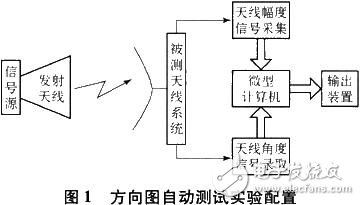
The automatic measurement of the pattern is the same as the manual measurement. The difference is the automation of data acquisition, processing and pattern drawing using electronic and computer technology. Figure 1 shows the experimental configuration of an automatic test of a radar antenna pattern.

The automatic measurement of the pattern is a dynamic measurement. During the measurement, the antenna under test continuously rotates, and receives the microwave signal transmitted by the signal source through the horn antenna. The receiving signal is sent to the antenna amplitude signal acquisition circuit, which is sent after conversion amplification and A/D conversion.
Give the computer. While the antenna is rotating, the antenna angle signal acquisition device converts the antenna position into an angle digital signal and sends it to the microcomputer. In this way, the amplitude signal level of each position in the measurement range can be obtained. According to the data, the microcomputer can perform data processing and output the calculation result by the output device.
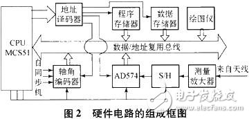
2 hardware circuit designThe system hardware includes a microcomputer control part, an antenna amplitude signal acquisition device, an antenna angle signal acquisition device, and a plotter. The block diagram of the composition is shown in Figure 2.

2.1 Microcomputer control circuit
The microcomputer control circuit adopts 51 series single-chip microcomputer, which is composed of CPU, program memory, external data memory and address decoder [2].
2.2 Antenna amplitude signal acquisition device
The amplitude signal acquisition device is composed of a measurement amplifier, a sample/hold circuit s/H, and an A/D conversion circuit.
The microwave signal received by the antenna is sent to the measuring amplifier, and the microwave signal is subjected to high-frequency detection, and the square wave signal is outputted, and then amplified, detected, filtered, etc., and a DC signal with a satisfactory amplitude and good waveform is output. The signal is sent to the A/D after sampling S/H. The A/D converts the analog signal into a digital signal under the control of the single-chip microcomputer, and stores it in an external data memory, thereby completing the acquisition of the amplitude signal.
The measuring amplifier is a signal conversion amplifying circuit of the system, which has high sensitivity, large dynamic range, stable working characteristics and fast response speed.
The selection principle of S/H is: If the change of the input signal level during A/D conversion is less than 1 LSB, S/H may not be added; otherwise, S/H must be added. The following equation is the relationship that the rate of change of the signal should be satisfied without adding S/H:

In the formula:  The relation is the absolute value of the rate of change of the signal; Vm is the full-scale voltage of A/D; n is the number of bits of A/D; and T is the conversion time of A/D.
The A/D chip adopts AD574, and its parameters are: Vm=10 V, n=12, T=25μs, substituting type (1)  Relationship. The maximum rate of change of the radar beam is not less than 10 V / (.), the antenna speed is generally not less than 2 r / min, the signal voltage change rate is not less than: 10 & TImes; (2 & TImes; 360 / 60) = 120 V / s, exceeding The limit is 97.7 V/s, so S/H must be added.
The AD574 has the advantages of small quantization error (2.44 mV), large dynamic range (72 dB), and high conversion speed (25 μs).
Laser radar contains LSPD safety laser scanner and LS laser radar. LSPD safety laser scanner is type 3 with CE certificate. It can be used for agv safety and industrial area protection. LS laser radar is for agv guide. Many famous agv manufacturers has installed LS laser radar to guide their agvs. Our cooperating brand contains Quicktron, Mushiny, Aresbots, etc. Feedback from customers are quite posotive.
Laser Radar,Auto Guided Vehicle Guide Radar,Sick Laser Radar,Safety Scanner,Safety Laser Scanner,Ls Series Laser Radar
Jining KeLi Photoelectronic Industrial Co.,Ltd , https://www.sdkelien.com