Brushless DC (BLDC) motors have many advantages over induction motors. The BLDC motor supports stepless speed change, which improves energy efficiency and reduces noise. The speed-torque characteristic of the BLDC motor is straight, which allows the motor to operate at lower speeds without the need to consume higher currents to produce the same torque.
This article will discuss the use of Microchip's PIC18FXX31 family of microcontrollers for sensory and sensorless control of BLDC motors in refrigerators.
This article refers to the address: http://
BLDC motor control
The rotor of the BLDC motor has permanent magnets alternately arranged in the north pole (N) and the south pole (S). The stator is formed by stacking the rigid sheets, the winding coils are placed in the slots, and the slots are cut along the edges of the shaft. To rotate a BLDC motor, the stator windings should be excited in a certain order. In order to perform the commutation sequence, it is important to know the rotor position. The rotor position is detected using a Hall effect sensor embedded in the stator. Most motors embed three Hall sensors on the non-drive end of the stator. Whenever the rotor pole is close to the Hall sensor, the sensor generates a high or low signal indicating that the N or S pole is close to the sensor. Based on the signal combinations of the three Hall sensors, an accurate commutation sequence can be determined. Table 1 gives a typical commutation sequence corresponding to the Hall sensor input.
Commutation sequence
As shown in Table 1, each sequence connects two phases of the three phases to the power supply and the third phase remains open. Figure 1 shows a simplified block diagram of the BLDC motor control. In this example, Microchip's PIC18F2331 flash microcontroller is used to control the power switch. The matching driver is used to drive the power switch accordingly. The PIC18Fxx31 family features six Pulse Width Modulation (PWM) channels with programmable PWM frequency and duty cycle. The Q0 to Q5 connections form a three-phase inverter bridge. The A phase, the B phase, and the C phase are respectively connected to the midpoint of each half H bridge, and the PWM0 to PWM5 respectively control the power switches Q0 to Q5. The PIC18Fxx31 family has three input capture pins, designated IC1, IC2, and IC3. The input capture module has an operating mode in which the value of Timer5 is captured each time a level change occurs on any of the input capture pins. This mode is suitable when connecting a Hall sensor to a microcontroller. Each time the Hall sensor changes its level, an interrupt is generated and the value of Timer5 is captured. This capture value corresponds to the motor speed.
Table 1: Typical commutation sequence corresponding to a Hall sensor 
When the signals marked by PWM0 to PWM5 are turned on or off according to the sequence, the motor will run at the rated speed (see Figure 1). This assumes that the DC bus voltage is equal to the sum of the rated voltage of the motor and all voltage losses across the switch. To change the speed, these signals can be pulse width modulated so that the signal frequency is much higher than the motor frequency. In general, the PWM frequency should be at least 10 times the maximum frequency of the motor. When the duty cycle of the PWM frequency is changed in the sequence, the average voltage supplied to the stator is lowered, thereby reducing the speed.
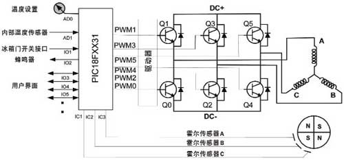
Figure 1 Motor control block diagram
There are other advantages to using a PWM to control the motor. When the DC bus voltage is much higher than the rated voltage of the motor, the voltage supplied to the motor can be limited to the rated voltage of the motor by limiting the PWM duty cycle to the PWM duty cycle corresponding to the rated voltage of the motor. In this way, the refrigerator control circuit can be used in multiple countries with different AC inputs. The AC voltage input is converted to DC using a diode bridge rectifier, and the controller's average voltage output is matched to the motor's rated voltage by controlling the PWM duty cycle.
There are several different ways of controlling. If the PWM signal is limited in the microcontroller, the upper switch can be turned on during the corresponding sequence, and the corresponding lower switch can be controlled by the required PWM duty cycle.
In Figure 1, the temperature is set by the user. The internal temperature of the refrigerator is measured using a temperature sensor. Depending on the size of the refrigerator, there may be multiple sensors located at different locations inside the refrigerator. The set temperature and actual temperature are read using an Analog-to-Digital Converter (ADC). When the temperature difference is greater than the predefined temperature hysteresis value (usually less than 2 degrees Fahrenheit), the motor will start rotating at a slower speed. If the temperature difference is large (for example, the refrigerator door is open), the motor should run at a higher speed. The relationship between temperature difference and speed can be determined according to the size of the refrigerator. When the temperature difference between the set temperature and the actual temperature changes, the compressor and fan speed can be changed accordingly.
General purpose I/O pins are available on the PIC18F2331 for LEDs, LCDs, switches, relays, and keypads. Figure 2 gives a summary of the firmware in flow chart form.
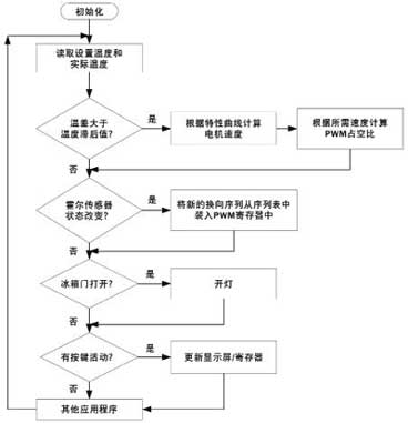
Figure 2 Flow chart for BLDC motor control using Hall sensor commutation
Sensorless control of BLDC motors
The sensorless control of the BLDC motor is commutated according to the Electro Motive Force (EMF) generated in the stator winding. This method does not require a Hall sensor. Sensorless control has two distinct advantages: higher reliability and lower cost.
Systems with fewer components are inherently more reliable. The compressor generates heat, and an increase in temperature accelerates the Hall sensor's malfunction or malfunction. In a sensorless design, not only Hall sensors are required, but also Hall sensor wiring is not required, which can result in cost savings (at least 5 wires can be omitted).
The back EMF signal (rather than the Hall sensor) commutates the BLDC motor. The magnitude of the back EMF depends on three factors: the angular velocity of the rotor, the number of turns in the stator winding, and the rotor field. After the motor design is completed, the rotor field and stator winding coil turns will remain constant. The factors controlling the back electromotive force are angular velocity or rotor speed. The back electromotive force is proportional to the rotor speed. However, for a given speed, the back EMF can be estimated using the back EMF constants provided in the motor data sheet.
Corresponding to the phase voltage, the relationship between the Hall sensor and the counter electromotive force is as shown in FIG. One winding is positively excited in each commutation sequence, the second winding is negatively excited, and the third remains open. As shown in Fig. 3, when the polarity of the counter electromotive force changes from positive to negative or from negative to positive, the Hall sensor signal changes state (there is a phase difference of 30°). Ideally, this condition occurs when the back EMF crosses zero. However, due to the winding characteristics, there will be a certain delay, which should be compensated by the MCU.
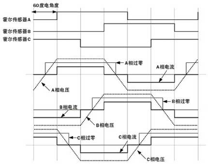
Figure 3 Relationship between Hall sensor signal, phase voltage, current and back EMF
Another area to consider is the work at very low speeds. Since the back electromotive force is proportional to the rotational speed, the back electromotive force for detecting the zero crossing is small when the speed is extremely low. When starting from the stop state, the motor needs to be started in an open loop. When sufficient back EMF is generated, sufficient to detect a zero crossing, the control should be switched to back EMF detection. The minimum speed at which the back electromotive force can be detected is calculated based on the back electromotive force constant of the motor.
Back EMF zero crossing detection
Detecting the zero-crossing of the back EMF is critical for sensorless control systems. Several different techniques can be used to determine the zero crossing. As mentioned earlier, each commutation sequence has a non-excited winding that detects the zero-crossing of the back EMF as each winding passes the non-excited state. Figures 4a, 4b and 4c show different solutions that can be used to detect the zero-crossing of the back EMF. In Figure 4a, phase A is connected to the positive pole of the power supply (DC+), phase C is connected to the negative pole of the power supply (or circuit DC-), and phase B is open. Observing the back electromotive force on phase B, it can be seen that the counter electromotive force rises toward a positive voltage and then decreases toward a negative voltage. A virtual zero crossing can be obtained when comparing it to half of the DC bus voltage. The zero crossing can be determined by using an op amp comparator.
Figure 4b shows a method for determining the zero-crossing of the back EMF by generating a virtual neutral point. The virtual neutral point is generated using the ladder resistor network shown in the figure, and then the back electromotive force in the non-excited winding is compared to the neutral point. This makes it possible to determine the zero crossings relatively easily at all measurable speeds.
Figures 4a and 4b show the zero-crossing detection circuit for phase B. For Phase A and Phase C, a similar circuit should be used for back EMF zero crossing detection when its corresponding winding is not energized.
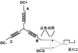
Figure 4a Back EMF Zero-crossing Detection: Comparison with DC Bus Voltage/2 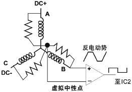
Figure 4b Back EMF Zero-crossing Detection: Comparison with Neutral Point 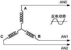
Figure 4c Back EMF Zero-crossing Detection: Reading with on-chip ADC
Another solution for back-EMF zero-crossing detection is to use an ADC, as shown in Figure 4c. The PIC18F2331 microcontroller has a high speed ADC for this purpose. By using a voltage divider, the back EMF signal can be reduced to a level that can be measured by the microcontroller. The signal is sampled using an on-chip ADC and the sampled value is continuously compared to a digital value corresponding to zero. When the two values ​​match, the commutation sequence is updated. The advantage of this method is that it makes the measurement more flexible. When the speed changes, the winding voltage may fluctuate, causing a change in the back electromotive force. In this case, the microcontroller can fully control the determination of the zero crossing. In addition, a digital filter can be used to filter out high frequency switching noise components in the back EMF signal.
in conclusion
The inherent advantages of BLDC motors allow them to be used to control compressors and fans in refrigerators, improve refrigerator energy efficiency and reduce noise, while supporting stepless shifting. However, the BLDC motor needs to be electronically commutated by a drive circuit. Variable speed operation is achieved using the drive circuit. In addition, the system consumes less power than the conventional way of intermittently starting and stopping the compressor according to the cooling load.
Using Microchip's PIC18F2331 family of microcontrollers, several methods for controlling BLDC motors in open-loop and closed-loop modes can be implemented, while taking advantage of the peripherals available in the microcontroller for motor control, reducing the amount of external hardware required.
Product categories of Universal Stylus Pen, We are Specialized Stylus Pen manufacturers from China, The Universal Stylus Pen can be worked on android phones / apple phones and all brands capacitive touch screens. We have perfect after-sale service and technical support. Looking forward to your cooperation.
Phone Stylus Pen,Touchscreen Stylus Pen,Stylus Pen For Android,Tablet Stylus Pen
Shenzhen Ruidian Technology CO., Ltd , https://www.wisonens.com