The voltage divider circuit is very common in electronic circuits, and it is widely used. It is important to understand the working principle of voltage division and the deformation circuit of voltage divider circuit, which has a significant impact on the analysis of many electronic circuits.
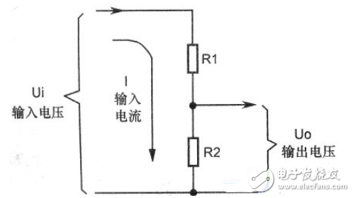
The resistor divider circuit is the most basic circuit in various voltage divider circuits. As shown in the above figure, it is a voltage divider circuit composed of resistors. Rl and R2 are two resistors in the voltage divider circuit.
There are two key points in analyzing the voltage divider circuit:
(1) Find the input. It is necessary to analyze where the input signal voltage is input to the sub-piezoelectric circuit, and how the specific input current loop is. The method of determining the input signal current loop in the circuit analysis is such that, starting from the input of the signal voltage, at least two components (not necessarily the resistors) reach the ground.
(2) Find the output, that is, which end point of the circuit the output voltage is taken from.
The signal voltage outputted by the voltage dividing circuit is sent to the next-stage circuit. Theoretically, the next-stage circuit input of the voltage-dividing circuit is the output of the voltage-dividing circuit, but the operability of using this method in the picture is poor because Sometimes it is difficult to analyze the input of the next-level circuit, so you can use a simpler method to analyze: find all the components in the voltage divider circuit, analyze from the ground to the upper end, find a component and voltage divider circuit When other circuits are connected, this connection point is the output of the voltage dividing circuit, and the voltage at this point is the output voltage of the voltage dividing circuit.
Resistance divider circuit analysis1. Resistor divider circuit
Figure 2-43 shows a typical resistor divider circuit. The LM324N circuit consists of two resistors, R1 and R2. The circuit has a voltage input and a voltage output.

This circuit feature distinguishes the voltage divider circuit from a number of circuits.
The input voltage is applied to the resistors R1 and R2, and the output voltage Uo is taken from the next resistor R2 in the series circuit. This type of circuit is called a voltage dividing circuit.
2. The working principle of the resistor divider circuit
There are two key points in analyzing the voltage divider circuit: one is to analyze the input voltage loop and find the input terminal; the other is to find the voltage output terminal.
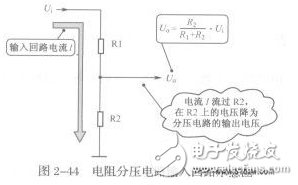
Figure 2-44 shows the input circuit of the resistor divider circuit. The input voltage is applied to resistors R1 and R2, and the current it produces flows through R1 and R2.
3. Find the output of the voltage divider circuit
The signal voltage outputted by the voltage dividing circuit is sent to the next stage circuit. In theory, the input end of the next stage circuit of the voltage dividing circuit is the output end of the voltage dividing circuit (the output end of the front stage circuit is the input end of the rear stage circuit). ). Figure 2-45 shows the relationship between the output of the preamplifier and the input of the post-stage circuit. However, the operability of this method in the picture is poor because it is sometimes difficult to analyze the input of the next stage circuit.
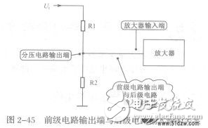
The easier way is as follows:
Find out that all the elements in the voltage divider circuit are connected to other circuits except the smog circuit. This connection point is the input of the voltage divider circuit. At the end, this voltage is the output voltage of the manure circuit.
4. Analysis method of output voltage magnitude
In the process of analyzing the voltage divider circuit, it is often necessary to find out the magnitude of the output voltage.
Calculation method of output voltage 分 of voltage divider circuit: Uo=R2/R1+R2·Ui
Where Ui is the input voltage; Uo is the output voltage.
Therefore, the output voltage is less than the input voltage. The voltage dividing circuit is two for attenuating the input signal voltage
Changing the value of Rl or R2 can change the magnitude of the output voltage Uo.
When analyzing the working principle of the voltage divider circuit, it is necessary not only to analyze the output voltage, but also to analyze the trend of the output voltage, because the resistance of the two resistors in the voltage divider circuit may change.
Figure 2-46 shows the change in the value of R2 resistance. When the input voltages Ui and R1 are fixed, if the resistance of R2 increases, the output voltage will also increase. When the resistance of R2 decreases, the output voltage Uo will also decrease.
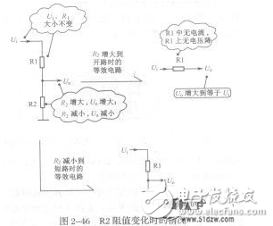
With the help of the extreme situation analysis, when the resistance value of R2 increases to open circuit, Uo=0V, that is, the output voltage of the voltage dividing circuit is equal to the input voltage; when the resistance value of R2 decreases to short circuit, Uo=OV, That is, the output voltage of the voltage divider circuit is equal to OV.
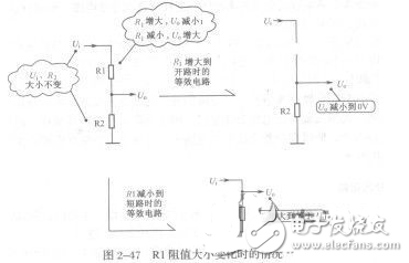
Figure 2-47 shows the change in the value of Rl resistance. The input voltages Ui, R2 are fixed, the output voltage Uo increases as the authority decreases, and the output voltage "decreases" as R1 increases.
Feature:
1.Superior uniformity and EV grade safefty LFP battery ;
2.Customized modular and large-scale ESS solution;
3.Reliable safety design and remote real-time monitoring;
4.High cost effective and short delivery duration.
mwh ,ess container, bess, commercial battery,battery container,mega,megawatt,Marine battery
Shenzhen Enershare Technology Co.,Ltd , https://www.enersharepower.com