Power electronics equipment consists of various types of power electronic circuits. Used for the transformation and control of high power energy. Also known as the converter device. It includes rectifiers, inverters, DC converters, AC converters, various power supplies and switches, motor speed control devices, DC power transmission devices, induction heating devices, reactive power compensation devices, electroplating electrolysis devices, and household appliances. Device, etc.
Among them, the DC power supply can be composed of a rectifier or a DC converter, and is used for power supply of DC motor speed regulation, charging (recharge power supply), electroplating, and scientific instruments. The AC power supply can consist of a frequency converter (see AC conversion circuit). Divided into variable frequency variable voltage power supply (for AC cage asynchronous motor speed regulation), constant frequency constant voltage power supply (used to constitute AC uninterruptible power supply), AC regulated power supply, medium frequency induction heating power supply (power output frequency up to 8 kHz For induction heating and quenching), high-frequency heating power supply (power output frequency higher than 8 kHz, used for quenching and welding). Using the fast switching performance of power electronics, a static contactless high-power switch can be constructed to replace the traditional electromagnetic contact high-power switch.
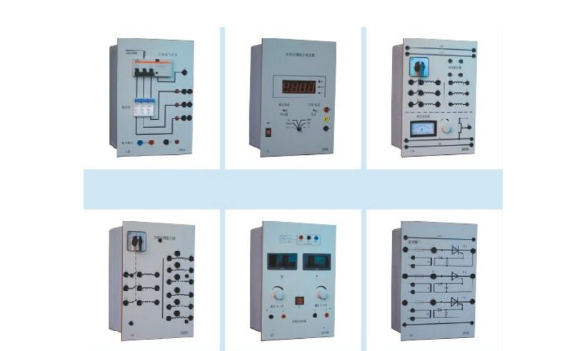
Power electronic devices are affected by the performance of the devices used, and the ability to withstand overvoltage and overcurrent is relatively poor. For example, motors, transformers, etc. can typically operate for several seconds or minutes at several times the rated current, while under the same conditions power electronics can be damaged in less than 0.1 seconds or less. Therefore, in addition to reasonable selection of the voltage and current capacity of the device when designing the power electronic device, special protection measures must be taken to prevent the device in the device from being damaged due to overcurrent and overvoltage. Some power electronic devices have special requirements for environmental conditions (such as temperature, cooling water pressure, wind speed, etc.), and these conditions need to be monitored to ensure reliable operation of the device.
Overvoltage protection of power electronic devicesOvervoltage can cause damage to the insulation of the unit and will not work. Common overvoltage protection measures are:
1 uses a RC absorption circuit. The capacitor and the resistor are connected in series, and the capacitor is used to absorb the overvoltage of the spike state, and the resistor connected in series with the capacitor consumes the energy of the overvoltage, thereby suppressing the oscillation of the circuit.
2 Select a nonlinear resistance device. The use of such devices is close to the volt-ampere characteristics of the Zener diode and its characteristics can be automatically restored after breakdown, thereby achieving overvoltage protection of the power electronic device. Commonly used devices are selenium stack overvoltage suppressors and varistors.
3 using electronic circuits for voltage detection and protection.
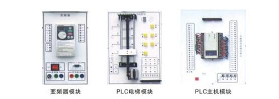
The power electronic device is a high-power electric energy conversion device, and there is inevitably serious electromagnetic interference at the installation and use site. In addition to directly causing the power electronic device to malfunction, the strong interference signal intrusion device mainly interferes with the control circuit of the device, causing the device to malfunction. Common technical measures for anti-jamming are:
1 suppress the intensity of the interference signal. For example, the AC relay and the AC contactor contact shunt capacitor can reduce the spark interference when the contact is turned on and off.
2 Reasonable wiring to reduce the distributed capacitance, distributed inductance and mutual inductance between the wires to prevent interference signal intrusion.
3 Implement electromagnetic shielding.
4 Correctly select the grounding point and ground it well.
5 strengthen the anti-interference ability of the circuit itself. The design uses electronic components with good anti-interference performance.
6 When the control circuit shares the DC regulated power supply, each part of the circuit should be a separate lead.
7 Minimize the input and output impedance of each unit circuit under the condition of signal strength.
8 Isolation means such as transformer coupling is used to isolate the control circuit from the signal source or control circuit and the main circuit of the power electronic device to prevent interference signal intrusion.
Ethernet Passive Optical Network (EPON), as the name implies, is a PON technology based on Ethernet. It adopts point-to-multipoint structure, passive optical fiber transmission, and provides multiple services on Ethernet. EPON technology is standardized by the IEEE802.3 EFM working group. In June 2004, the IEEE802.3EFM working group released the EPON standard-IEEE802.3ah (incorporated into the IEEE802.3-2005 standard in 2005). In this standard, the Ethernet and PON technologies are combined, the PON technology is used in the physical layer, the Ethernet protocol is used in the data link layer, and the PON topology is used to realize Ethernet access. Therefore, it combines the advantages of PON technology and Ethernet technology: low cost, high bandwidth, strong scalability, compatibility with existing Ethernet, and convenient management.
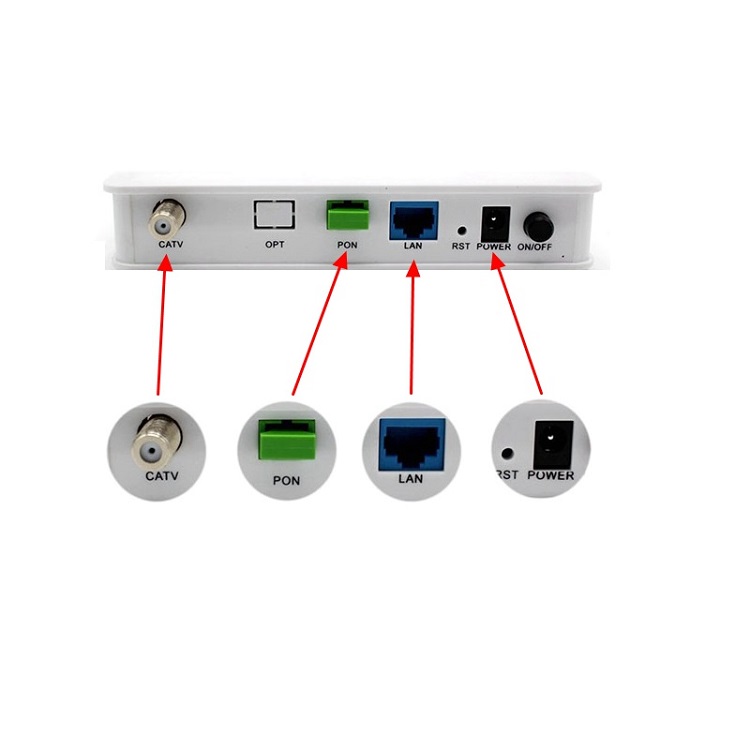
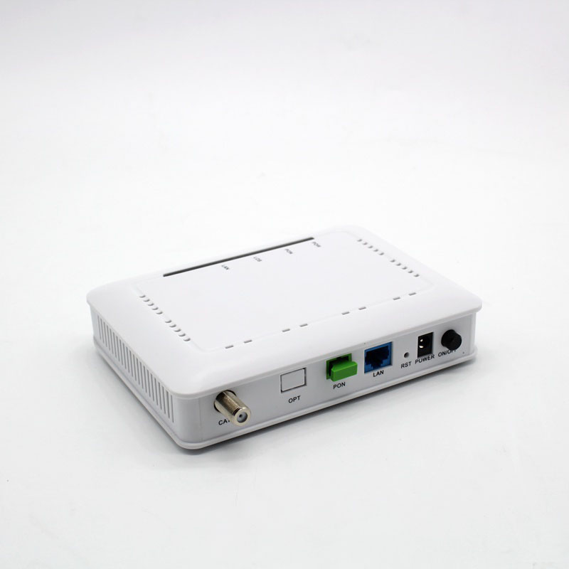
EPON RF ONU, CATV PORT ONU, CATV ONU, CATV EPON ONU
Shenzhen GL-COM Technology CO.,LTD. , https://www.szglcom.com