Designers can select one or more objects in the [Clock Regions] window, [I/O Ports] window or [Package Pins] window, or click the button to cancel all selections, and then run the [Tools] → [Clear Placement Constraints] command. Open the window shown in Figure 10-48. There are three options. [Instance placement] clears the layout plan of the instance, [I/O port placement] clears the I/O port layout plan, and [Both] both objects are cleared.
In this example, we select a specific Pin foot in the [Package Pins] window to select [I/O port placement] as an example.
![[Clear Placement Constraints] window](http://i.bosscdn.com/blog/0F/01/2S/28_0.png)
Figure 10-48 [Clear Placement Constraints] Window
Click the [Next] button to open the dialog box shown in Figure 10-49. Select the [Unplace selected port] option, click [Next], open the dialog box shown in Figure 10-50, select [Unplace one fixed port], click the [Next] button, click [Finish] in the window that appears, clear An I/O constraint.
It should be noted that the operation process here will select several objects depending on whether the designer has selected the object, and the operation interface is slightly different.
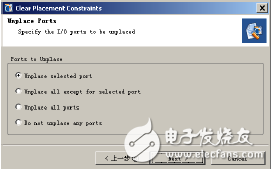
Figure 10-49 Specifying I/O constraints to be cleared
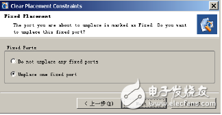
Figure 10-50 prompts to clear a fixed type of port
Sixth, establish and configure I / O portSelect [Create I/O Ports...] in the right-click menu of the [I/O ports] window, and the dialog box shown in Figure 10-51 will pop up. Enter the port name such as port_1 to change the port properties or create a bus type port. . Click the [OK] button to see that a port has been added to the [I/O ports] window.
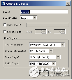
Figure 10-51 Establishing an I/O port
The configuration of the I/O port is similar. Select [Configure I/O Ports...] from the right-click menu.
Seven, establish a management interface for I / O portsMaximize the [I/O Ports] window, select all ports of *USB_0*, run the right-click menu command [Create I/O Port Interface...], enter usb0_interafce in the pop-up dialog box, as shown in Figure 10-52, click [ OK], you can see that these *USB_0* ports have a management interface named usb0_interface, as shown in Figure 10-53. Using this method, PCB management can be facilitated.
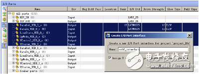
Figure 10-52 Establishing an I/O port interface
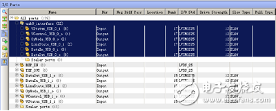
Figure 10-53 Established I/O Port Window
Eight, allocate I / O portPlanAhead provides a variety of methods for allocating I/O ports, which can be automatically assigned, as well as several semi-automatic allocation methods, such as assigning I/O ports to an I/O Bank [Place I/O Ports in an I/O Bank ], assign I/O ports to a specified area [Place I/OPorts in an Area], and sequentially assign I/O ports [Place I/O Ports SequenTIally].
It should be noted that in order to ensure the correctness of I/O allocation, it is necessary to turn on the automatic DRCs check function of I/O allocation before performing I/O allocation. Execute [Tools] → [OpTIons] → [General] to open the [AutomaTIcally enforce legal I/O placement] function.
1. Automatically assign I/O ports.
You can complete the automatic assignment of I/O ports by running [Tools] → [Autoplace I/O Ports].
2. Place the I/O port in an I/O Bank.
In the [I/O ports] window shown in Figure 10-53, select the usb0_interface port, run [Place I/O Ports in an I/O Bank] in the right-click menu, or click the button in the [Package] window. Paste the pin associated with usb0_interafce to the mouse, drag the mouse in the [Package] window, find the appropriate location and click the left mouse button to complete the I/O port assignment.
Clear the allocation to the usb0_interface port to facilitate the following operations.
3. Place the I/O port in a zone.
In the [I/O ports] window shown in Figure 10-53, select the usb0_interface port, run [Place I/O Ports in an Area] in the right-click menu, or click the button in the [Package] window. Package] Drag the mouse to draw a rectangular box suitable for all I/O ports, and release the mouse to complete the I/O port assignment.
Clear the allocation to the usb0_interface port to facilitate the following operations.
4. Place the I/O ports in sequence.
In the [I/O ports] window shown in Figure 10-53, select the usb0_interface port, run [Place I/O Ports SequenTIally] in the right-click menu, or click the button in the [Package] window. At this time, you can use [Package]. Drag the mouse over the window to place all I/O ports in order until all I/O ports are allocated. It should be noted that the description here is the synthesis of the pre-I/O port allocation, the application is a CSV file, there is no comprehensive netlist, the clock pins, high-speed transceivers and differential pairs are not automatically processed by the tool, therefore, such Special attention is required when assigning pins.
500W Solar Generator
All In One Solar Power System
AC power supply to be widely applied to small solar power generation occasions including families, schools, street monitoring, forest monitoring,industrial and mining enterprises, frontier defense sea islands, pasturing areas,etc.
Off Grid Solar Panel Energy System 500W 1000W DC Portable Mini Small Light Solar Power Home Lighting System Kits Solar Generator for Indoor Outdoor

500W Solar Generator,Off Grid Solar Generator,Portable Solar Generator For Outside,Best Hot Sale Solar Generator
suzhou whaylan new energy technology co., ltd , https://www.whaylan.com