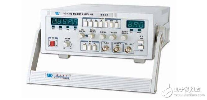
A function signal generator is a device that provides electrical signals at various frequencies, waveforms, and output levels. Used as a signal source or excitation source for testing when measuring the amplitude characteristics, frequency characteristics, transmission characteristics, and other electrical parameters of various telecommunication systems or telecommunication devices, as well as measuring the characteristics and parameters of components.
Function signal generators, also known as signal sources or oscillators, have a wide range of applications in production practice and technology. Various waveform curves can be represented by trigonometric equations. A circuit capable of generating a variety of waveforms such as a triangular wave, a sawtooth wave, a rectangular wave (including a square wave), and a sine wave is called a function signal generator.
The function of the function signal generator:A function signal generator is a device that provides electrical signals at various frequencies, waveforms, and output levels. Used as a signal source or excitation source for testing when measuring the amplitude characteristics, frequency characteristics, transmission characteristics, and other electrical parameters of various telecommunication systems or telecommunication devices, as well as measuring the characteristics and parameters of components. It can generate a variety of waveforms, such as triangular waves, sawtooth waves, rectangular waves, sine waves, so it has a wide range of applications in production practice and technology.
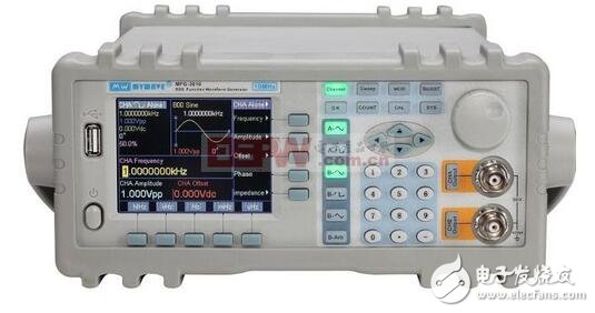
The function signal generator system is mainly composed of a main vibration level, a main vibration output adjustment potentiometer, a voltage amplifier, an output attenuator, a power amplifier, an impedance converter and an indicator voltmeter. When the input terminal inputs a small signal sine wave, the signal is transmitted in two ways, one completes the rectification voltage multiplication function to provide the working power supply; the other enters the input end of an inverter to complete the signal amplification function. The amplified signal is processed by a gate circuit of a subsequent stage, converted into a square wave and outputted, and the output end is an adjustable resistor.
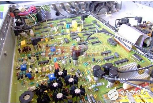
The various waveform curves generated by the function signal generator can be represented by trigonometric function equations. The function signal generator has a very wide range of applications in circuit experiments and equipment detection. For example, in communication, broadcasting, and television systems, RF transmission is required. The radio frequency wave here is a carrier wave. When an audio, video signal or pulse signal is carried out, an oscillator capable of generating a high frequency is needed. In the fields of industry, agriculture, biomedicine, etc., such as high-frequency induction heating, melting, quenching, ultrasonic diagnosis, magnetic resonance imaging, etc., all require large or small, high or low frequency oscillators.
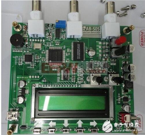
The signals provided by technology and industrial applications are becoming more and more sophisticated. The introduction promotes the development and promotion of function signal generators and becomes an indispensable tool in industrial production, product development, scientific research, etc. As a sophisticated test instrument, It has been widely used in the electronics industry. According to the principle analysis of the function signal generator, we know that the most commonly used is that we often use the sawtooth signal generator as the time base circuit.
For example, if we need to measure the accuracy/performance/frequency of a certain signal, we need to find a signal to refer to the motion law of the observed detection signal, and then use some display instruments (such as oscilloscope/digital display instrument) to display the measured image by using the fluorescent screen. The image of the function signal generator is compared to simplify the function generator measurement. Below I summarize some basic knowledge about function signal generators, including function signal generator principles and performance analysis, so that everyone can understand this instrument more intuitively.
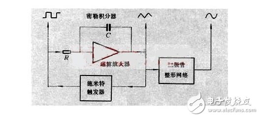
The function signal generator is used to test or repair the frequency characteristics, gain, and passband of the low frequency amplifier in various electronic equipment, and can also be used as an external modulation signal source for the high frequency signal generator. As the name implies, it is possible to generate a function signal source, such as a sine wave of a certain frequency, and some may have a voltage output or a power output. Below we use a simple example to illustrate the principle of the function signal generator.
a) The signal generator system is mainly composed of the following parts: main vibration level, main vibration output adjustment potentiometer, voltage amplifier, output attenuator, power amplifier, impedance converter (output transformer) and indicating voltmeter.
b) Working mode: When the input terminal inputs a small signal sine wave, the signal is transmitted in two ways, one path loop completes the rectification voltage multiplication function, provides the working power supply; the other path capacitively couples into the input of an inverter End, complete the signal amplification function. The amplified signal is processed by a gate circuit of a subsequent stage, converted into a square wave, and output. The output is an adjustable resistor.
c) Work flow: First, the main vibration level generates a low-frequency sinusoidal oscillation signal, and the signal needs to be amplified by a voltage amplifier. The amplification multiple must reach the voltage output amplitude requirement. Finally, the output attenuator directly outputs the voltage that the annunciator can actually output. The output voltage can be adjusted with the main oscillator output potentiometer.
It is generally managed by a single-chip microcomputer, mainly to achieve the following functions:
a) controlling the frequency generated by the function generator;
b) controlling the waveform of the output signal;
c) measuring the frequency of the output or measuring the frequency of the external input and displaying it;
d) measuring the amplitude of the output signal and displaying it;
e) Control the output of a single pulse.
Let's take an example. We use the power-adaptive square wave generator schematic to give a detailed explanation. The picture below shows a square wave generator that does not require a power supply and can be used as a simple source for electronics enthusiasts and laboratories.
This circuit is an adaptive square wave generator consisting of a six-inverter CD4096. The square wave generator circuit is simple and easy to manufacture, so the square wave generator circuit can be used as a 50 Hz square wave generator powered by a commercial power supply. At the time of production, the 220V sine wave of the mains should be processed by the transformer isolation buck (1~0.75V) and input to the input end of the circuit to ensure safety.
[Circuit analysis is as follows]
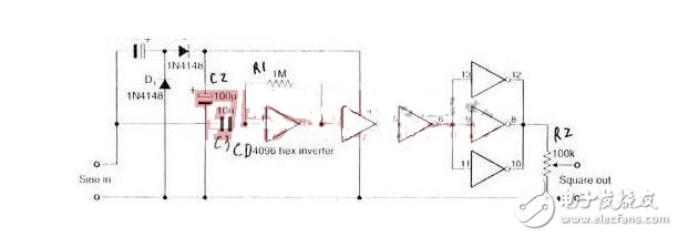
(1) When the input terminal inputs a small signal sine wave, the signal is transmitted in two ways, and one of the paths C1, D1, D2, and C2 loops completes the rectification voltage multiplication function, and provides working power to the CD4096;
(2) Another path capacitor C3 is coupled to enter the input of an inverter of CD4096 to complete the signal amplification function (the inverter can be used as an amplifier when the small signal is working). The amplified signal is processed by the gate circuit of the subsequent stage, converted into a square wave and output through the 12, 8, and 10 pins of the CD4096. The output R2 is an adjustable resistor to ensure that the output signal is adjustable from 0 to 1.25V.
In the electronic design, the function signal generator is often used, and can provide sine waves, square waves and triangular waves of a certain frequency at a certain frequency.
How to build a complete function generator architecture:The function signal generator has great use in the field of analog electronics. To sum up, the implementation of the function signal generator usually has the following types:
(1) Function generator composed of discrete components: usually a single function generator and the frequency is not high, its operation is not very stable, and it is difficult to debug.
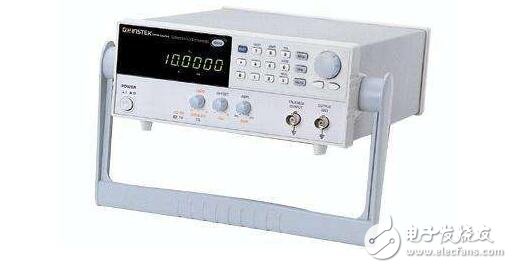
(2) It can be fabricated by general-purpose devices such as transistors and op amp ICs, and more by special function signal generator ICs. Early function signal generator ICs, such as L8038, BA205, XR2207/2209, etc., have fewer functions, less precision, and the upper frequency limit is only 300 kHz, which cannot generate higher frequency signals, and the adjustment method is not flexible enough. The air ratio cannot be adjusted independently, and the two affect each other.
(3) Function generator using monolithic integrated chip: It can generate multiple waveforms, achieve higher frequency, and is easy to debug. In view of this, the US company has developed a new generation of function signal generator ICMAX038, which overcomes the shortcomings of the chip in (2) and can achieve higher technical specifications, which is beyond the reach of the above-mentioned chips. The MAX038 has a high frequency and high accuracy, so it is called a high-frequency precision function signal generator IC. The MAX038 is the preferred device for the design of circuits such as phase-locked loops, voltage-controlled oscillators, frequency synthesizers, and pulse width modulators.
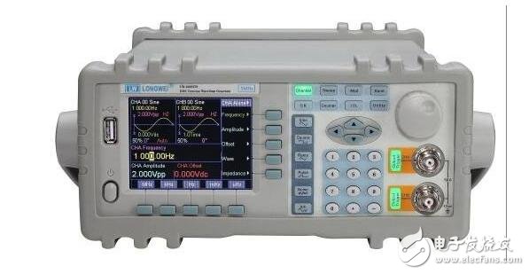
(4) Function generator using a dedicated direct digital synthesis DDS chip: capable of generating arbitrary waveforms and achieving high frequencies. But the cost is higher.
Vape By Puffs,Disposable Light Vape,Disposable Device Pen,Vape Pod Smoke
Guangzhou Yunge Tianhong Electronic Technology Co., Ltd , https://www.e-cigarettesfactory.com