A waste electronic watch can be made into a test pencil. Disassemble the outer casing and the three parts of the movement are shown below.
First, making display components
On the circuit board below, the "black glue" is sealed with an electronic watch chip. First, the sticker is cut into a width of 4mm and a length of 18mm, and the liquid crystal pin line under the conductive rubber is covered, and the inner part of the virtual frame of the circuit board is flattened with the brocade.

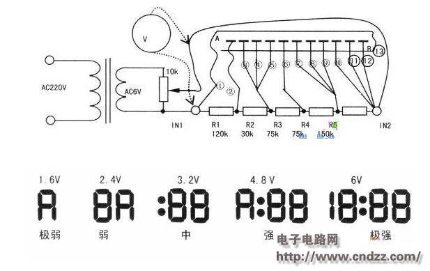
"Black glue" is harder and can be heated and then heated. Then, take the electrode out and solder it on, as shown on the right. The LCD screen has 13 pins, sorted from left to right to 1, 2...10, from 1, 2, 3-4-5, 6, 7-8-9, 10-(11)-(12) Leads to 6 copper wires, (13) feet and 1 foot. Connect B to the A foot through the upper copper clad plate. The chip resistors R1 to R5 are connected between the six copper wires, and are respectively led from the first pin and the ten pin to the original battery terminals IN1 and IN2, as shown in FIG. Note: The resistance is in the 0805 or 0603 size specification and is concentrated on the original vinyl position to install the plastic case. After the welding is completed, remove the sticker and wipe the LCD lead with a cotton swab dipped in water. Finally, the board, the LCD screen, and the conductive rubber are mounted to the original position, and the outer casing is closed.

Second, display component debugging
As shown in the figure above, for IN1 and IN2, 6V adjustable AC power supply is provided, and the potentiometer is adjusted to 1.6V, 2.4V, 3.2V, 4.8V, and 6V respectively. The LCD screen is shown below.
If the missing segment is displayed, the conductive rubber is not in good contact or the liquid crystal lead of the circuit board is soldered. If the upper or lower half is not displayed, it means that A and B are not connected, that is, (13) and 1 are not connected. If the right side is constant, the left side is not visible, there may be a resistance solder joint, check the resistance between IN1 and IN2 (450k). If the 1.6V, 2.4V - - grading error is greater than 20qo, check if the resistance is wrong and there is no short circuit between the liquid crystal pins.
If there is no transformer, the IN1 string IOMQ resistor can be connected to the 220V line, and the IN1 is held in the hand and the LCD screen is displayed in full. If the missing segment is displayed, the debugging method is the same as above.
Third, make amplifying components
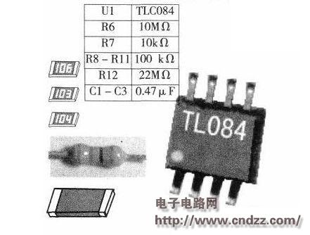
Pay attention to the production of the amplification components: Ul can not use LM358, optional TLC272, TLC2272, TLC27L2, TLV2262, etc., TLC27L2, TLV2262 performance is more suitable for this production. 
Fourth, debug amplifying components
Check the welding of each component is correct, plus 9V power supply, use the digital multimeter DC20V file to measure the DC voltage: 8 feet for 9V, 7 feet for 1.5~5V, 4 feet for OV, 1, 2, 3 feet for about 4.5V. Use the electric iron head to approach or touch the R12. Use the AC 20V to measure the 1 and 7 feet and immediately have readings, such as 1V, 2V, etc., indicating that the amplifier has amplified the AC signal. Because the input impedance of the Ul4 pin is particularly high, and the probe is close to the AC live line, assuming that the capacitance between the live line and the probe is O.OOOIPF, the input impedance of the Ul5 pin is lOpF, then 220V has one hundred thousandth of the sensed pole. After 1000 times magnification, the output is about 2V. If the sensitivity is found to be too high, increasing the R7 to 22kQ, 51kQ can reduce the magnification. Use a single-core wire, one end welded to the negative pole of the battery, the other end around the R12 a few turns, can also shield the stray electric field, increase the input capacitance, the effect is very obvious. 

Five, practical application
Example 1 judges "zero-fire-ground". When the probe is close to the “ground†on the top of the socket, it does not display or display “very weakâ€; if the metal inside the contact is “strong†or “extremely strongâ€, the grounding of the wall socket is poor. The "fire" of the probe near the right side of the socket should show "strong" and "extremely strong"; the probe should be close to the "zero" on the left side of the socket, and should not display or display "very weak"; if the phenomenon is mutual, it means that "zero-fire" is inverted. .
Example 2 checks the line. Turn on the load side of the trace, and the probe is close to the slot plate of the faulty trace or the dark line inside the wall and move along the slot plate. If the LCD screen suddenly changes from "strong" to "weak", the line breakpoint is found. If the display is "strong", the breakpoint may be at the zero line, the LCD screen is "strong" before the breakpoint, and then "extremely strong" after the breakpoint, or "middle" before the breakpoint, and "strong" after the breakpoint. That is, the breakpoint of the zero line. Similarly, you can find the break point of the electric blanket, as shown below. 
Sixth, making passive induction measuring pen
The electronic watch LCD can also be fabricated as passive inductive power measurement without the need for batteries and operational amplifiers. Disconnect "X", that is, A and B are not connected, and B is separately drawn as IN3, as shown in the figure above.
Usage 1 Use the probe to contact the metal casing of the appliance, the hand shaker 1, the human body as the ground, this measurement method belongs to single-ended measurement. 1 can judge the zero line or the hot line; 2 can measure the AC voltage is high or low? The relationship between voltage and voltage is shown as follows; 3 can detect the leakage of the electrical enclosure. If the probe is connected to the enclosure, 55V indicates that the enclosure is not connected to the ground, but will not shock the person. The housing does not show that the housing is well grounded. If the outer casing shows 180V or more, there may be leakage of the outer casing and the live wire, and there is a danger of electric shock.
Usage 2 Inductive measurement method, the probe is close to the wire sheath, and the hand is connected to the pole 2. There is a display indicating that the insulation is a hot wire, and vice versa. It is also possible to detect breaks in the slot plate. To enhance the sensitivity, a thick wire (shown by the dashed line in the figure above) can be soldered on the probe head and parallel to the wires in the slot plate to increase the distributed capacitance. Since the liquid crystal structures of different electronic meters are slightly different, the display patterns are not necessarily identical.

More about TLC084 device data: IC query network http://
Power Bank
Power Bank,solar power bank,Cell Phone Portable Charger,Portable Power Bank for Laptop
Pogo Technology International Ltd , https://www.wisesir.net