Schematic diagram and application diagram of thyristor SCR is the abbreviation of thyristor rectifier component. It is a four-layer high-power semiconductor device with three PN junctions, which is generally formed by reverse connection of two thyristors. Its function is not only rectification, but also can be used as a quick switch-on or cut-off of a non-contact switch; an inverter that converts direct current into alternating current; an alternating current of one frequency into an alternating current of another frequency, and the like. Like other semiconductor devices, thyristors have the advantages of small size, high efficiency, good stability, and reliable operation. Its emergence has made semiconductor technology enter the field of strong electricity from the field of weak electricity, and has become a component used in industry, agriculture, transportation, military research, commercial and civil appliances. At present, thyristors are widely used in automatic control, electromechanical applications, industrial electrical appliances and home appliances.
The thyristor is mainly divided into three types: a spiral type, a flat type and a flat bottom type. There are many spiral applications.
The thyristor has three poles - an anode (A), a cathode (C) and a gate (G). The die is a four-layer structure in which a P-type conductor and an N-type conductor overlap, and has three PN junctions. The silicon rectifier diode with only one PN junction is structurally quite different. The introduction of the four-layer structure of the thyristor and the control electrode laid the foundation for its excellent control characteristics of “small controlâ€. For thyristor applications, a large anode current or voltage can be controlled by adding a small current or voltage to the gate. It is now possible to manufacture thyristor components with current capacities ranging from a few hundred amps to thousands of amps. Generally, the thyristor below 5 amps is called a small power thyristor, and the thyristor above 50 amps is called a high power thyristor. 
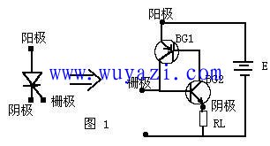
We can look at the first, second, and third layers from the cathode upwards to be an NPN type transistor, and the second, third, and fourth layers constitute another PNP type transistor. The second and third layers are shared by two tubes. The equivalent circuit diagram of Figure 1 can be drawn. When a forward voltage E is applied between the anode and the cathode, and a positive trigger signal is input between the gate G and the cathode C (equivalent to the base of the BG2), the BG2 will generate a base current Ib2. Zooming in, BG2 will have a collector current IC2 that is amplified by a factor of two. Since the BG2 collector is connected to the base of BG1, IC2 is the base current Ib1 of BG1. BG1 in turn Ib1 (Ib2) amplifies the collector current IC1 of β1 and sends it back to the base of BG2 for amplification. This cycle is amplified until BG1 and BG2 are fully turned on. In fact, this process is “one-touchâ€. For thyristors, the trigger signal is applied to the control electrode, and the thyristor is turned on immediately. The conduction time is mainly determined by the performance of the thyristor.
After the thyristor is triggered to turn on, due to the cyclic feedback, the current flowing into the base of BG2 is not only the initial Ib2, but the current after amplification by BG1 and BG2 (β1*β2*Ib2). This current is very large. At Ib2, it is enough to keep the BG2 on. At this time, even if the trigger signal disappears, the thyristor remains in the on state. Only when the power supply E is turned off or the output voltage of E is lowered, so that the collector current of BG1 and BG2 is less than the minimum value of maintaining conduction, the thyristor can be Shut down. Of course, if the E polarity is reversed, BG1 and BG2 will be in the off state due to the reverse voltage. At this time, the thyristor does not work even if the trigger signal is input. Conversely, E is connected in the forward direction, and the touch signal is negative, and the thyristor cannot be turned on. In addition, if the trigger signal is not added, and the forward anode voltage is too large to exceed a certain value, the thyristor will also be turned on, but it is already in an abnormal working condition.
The controllable nature of the thyristor, which is controlled by the trigger signal (small trigger current) (the large current through the thyristor), is an important feature that distinguishes it from ordinary silicon rectifier diodes.
Since the thyristor has only two working states: on and off, it has switching characteristics, which require certain conditions to be converted. See Table 1 for this condition.
Table 1 thyristor turn-on and turn-off conditions
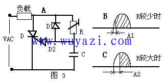
2. Phase trigger circuit:
The phase trigger circuit is actually a kind of AC trigger circuit. As shown in Figure 3, the circuit is controlled by the RC loop to control the phase of the trigger signal. When the R value is small, the RC time constant is less, the phase shift A1 of the trigger signal is less, so the load obtains larger electric power; when the R value is larger, the RC time constant is larger, and the phase shift A2 of the trigger signal is larger. Large, so the load gets less electrical power. This typical electric power stepless adjustment circuit is used in many electrical products in daily life.

The main parameters of thyristor are:
1. The average value of the rated on-state average current under a certain condition, the anode---the cathode can continuously pass the 50 Hz sine half-wave current.
2. The positive blocking peak voltage is not added to the trigger circuit when the control electrode is open. When the anode forward voltage has not exceeded the conduction voltage, the forward peak voltage across the thyristor can be repeated. The forward voltage peak of the thyristor cannot exceed the value given in the manual.
3. Reverse negative peak voltage When the thyristor is applied with a reverse voltage and is in the reverse-off state, the reverse peak voltage applied across the thyristor can be repeated. When used, the value given by this manual cannot be exceeded.
4. The minimum control pole current and voltage required for the control electrode to trigger the current at a specified ambient temperature and a certain voltage between the anode and the cathode to turn the thyristor from the off state to the on state.
5. Maintain the current at the specified temperature, control the open circuit, and maintain the minimum anode forward current necessary for the thyristor to conduct.
The control system of the lighting system is controlled by the thyristor technology: the voltage regulation speed is fast, the precision is high, the time can be adjusted in real time, the voltage regulation function is adopted, and the electronic component is relatively small in size, light in weight and low in cost. However, there is a fatal defect in the voltage regulation method. Due to the chopping, the voltage cannot realize the sine wave output, and a large number of harmonics appear, which form a harmonic pollution to the power grid system, which is extremely harmful and cannot be used in a capacitor compensation circuit. (Modern lighting design requirements stipulate that the power factor of the lighting system must be above 0.9, while the power factor of the gas discharge lamp is generally below 0.5, so the capacitors are designed to compensate the power factor.) In developed countries, it has been clearly stated that the electrical The limitation of harmonic content of equipment, in domestic, Beijing, Shanghai, Guangzhou and other big cities, has been restricted to the use of equipment with harmonic content exceeding the standard.
When the illuminance control of the illumination system is controlled by the thyristor technology, the filter device can be added to effectively reduce the harmonic pollution.
In recent years, many new thyristor components have been introduced, such as fast thyristors for high-frequency applications. Positive or negative trigger signals can be used to control two-way thyristors in both directions. Positive trigger signals can be used. It is turned on, a thyristor that is turned off with a negative trigger signal, and the like.
Application introduction ------ thyristor application in the dimmer:
The thyristor dimmer is the mainstream equipment in the field of stage lighting and ambient lighting.
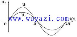
The various dimmers used in lighting systems are essentially an AC voltage regulator. Older transformers and varistor dimming are implemented by adjusting the magnitude of the voltage or current, as shown in the following figure. U1 is the unregulated 220V AC waveform. The voltage waveform after voltage regulation is u2. Because the amplitude is less than u1, the light is dimmed. In this dimming mode, although the amplitude of the sinusoidal alternating current is changed, the nature of its sinusoidal waveform is not changed.

Compared with transformers and resistors, thyristor dimmers have completely different dimming mechanisms. They use phase control methods to achieve voltage regulation or dimming. For a common reverse blocking thyristor, the thyristor characteristic is that when the thyristor is added with a positive anode voltage and an appropriate forward control voltage is applied, the thyristor is turned on; The pass will be maintained even after the gate control voltage is removed, until the reverse anode voltage or anode current is less than the thyristor's own holding current. Ordinary thyristor dimmers use this feature of thyristors to achieve leading edge triggered phase-controlled voltage regulation. At a certain time t1 (or a certain phase angle wt1) after the sine wave AC zero crossing, a trigger pulse is applied to the thyristor control electrode to turn on the thyristor, according to the thyristor switch characteristics described above. This conduction will be maintained until the end of the positive half cycle of the sine wave. Therefore, in the positive half cycle of the sine wave (ie, 0~p interval), the thyristor in the range of 0~wt1 is not turned on. This range is called the control angle, which is usually represented by a; and the thyristor is turned on between wt1 and p. This range is called the conduction angle and is usually represented by j. Similarly, in the negative half cycle of the sinusoidal alternating current, the other thyristor (for two unidirectional thyristor anti-parallel or triac) in reverse connection is applied at time t2 (ie, phase angle wt2). Trigger the pulse to turn it on. In this way, the conduction of the sine wave is controlled every half cycle to obtain the same conduction angle. If the application time (or phase) of the trigger pulse is changed, the magnitude of the conduction angle j (or the control angle a) is changed. The larger the conduction angle, the higher the voltage output from the dimmer, and the brighter the lamp. From the above thyristor dimming principle, the voltage waveform output by the dimmer is no longer a sine wave unless the dimmer is in a fully conducting state, that is, the conduction angle is 180° (or p). It is because the sine wave is cut and the waveform is damaged, which will cause interference to the power grid...
Good dimming equipment should take the necessary measures to reduce the interference caused by the use of thyristor technology.
ZGAR FIT
ZGAR electronic cigarette uses high-tech R&D, food grade disposable pod device and high-quality raw material. All package designs are Original IP. Our designer team is from Hong Kong. We have very high requirements for product quality, flavors taste and packaging design. The E-liquid is imported, materials are food grade, and assembly plant is medical-grade dust-free workshops.
From production to packaging, the whole system of tracking, efficient and orderly process, achieving daily efficient output. We pay attention to the details of each process control. The first class dust-free production workshop has passed the GMP food and drug production standard certification, ensuring quality and safety. We choose the products with a traceability system, which can not only effectively track and trace all kinds of data, but also ensure good product quality.
We offer best price, high quality Vape Device, E-Cigarette Vape Pen, Disposable Device Vape,Vape Pen Atomizer, Electronic cigarette to all over the world.
Much Better Vaping Experience!


E-Cigarette Vape Pen,Disposable Device Vape,Vape Pen Atomizer,Latest Disposable E-Cigarette OEM vape pen,OEM electronic cigarette
ZGAR INTERNATIONAL TRADING CO., LTD. , https://www.szdisposable-vape.com