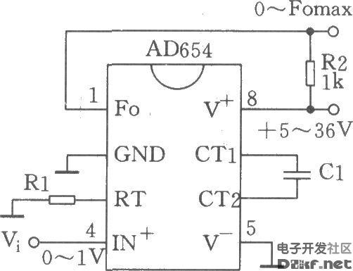
The figure shows the low-cost voltage-to-frequency converter (VFC) using the AD654. As long as the necessary components R1 and Cl are connected as shown, it can be a VFC application circuit. The power supply voltage can be as low as 4.5V to ensure performance, guarantee performance to l6.5V, and consume up to 3mA (no load). The highest frequency is 520kHz. The input voltage range is limited to 0 to 4V. The input range Vi is determined by the resistor R1, that is, Vi/Rl=lmA. For example, Vi=0~1V takes Rl=lkΩ, and Vi=0~5V selects Rl=5kΩ. The output corresponding frequency range is determined by Cl, Fomax=l/l0Cl, frequency unit kHz, and Cl unit is μF. For example, if Cl = 0.1 μF, the output frequency is 0 to 1 kHz; Cl = 0.001 > F, and the output frequency ranges from 0 to 100 kHz.
Guangdong Kaihua Electric Appliance Co., Ltd. , https://www.kaihuacable.com