Abstract: IME6400 is an integrated circuit chip developed by South Korea's INTIME that can support MPEG4 high-resolution real-time video encoding. The article introduces the performance characteristics of the IEM6400 chip, and gives a specific method of using the chip to design a digital video surveillance system based on an embedded PC core.
1 Overview
MPEG4 is a member of the Moving Picture Expert Group (Moving Picture Exchange Group) standard series and is a solution developed by the International Organization for Standardization for multimedia communications. The main feature of MPEG4 is to encode the content in the image. It has more advantages than MPEG2 encoding. To this end, South Korea INTiME company launched an integrated circuit chip IME6400 that can support the MPEG4 standard coding scheme, which triggered people to start using the integrated circuit to improve the speed and performance of the monitoring system. This article gives a brief introduction to the chip with the application of IME6400 in embedded system.
2 Performance characteristics of IME6400
IME6400 is a multi-channel digital audio and video coding system-level chip packaged in 240-pin PQFP. The chip can support MPEG4 / 2/1 video compression coding standard; it also supports I, P and B frame compression. The image size can be set by programming, the maximum size can reach 2048 × 2048; the code rate can support fixed and variable code rate compression, and supports dynamic detection.
IME6400 can support 48 / 44.1 / 32/24 / 22.05 / 16kHz audio sampling. Its synchronous serial interface is an optional external audio DSP. The external interface uses 32-bit to synchronize the DRAM bus interface and the 8 / 16bit external HOST interface. In addition? IME6400 requires an external clock of 27MHz.
3 The main pin functions of IME6400
3.1 SDRAM pin
The SDRAM interface in IME6400 can support 32bit synchronous DRAM bus interface. According to different needs, SDRAM with different sizes from 4Mbits to 64Mbits can be selected. When you need to support high-resolution, MPEG4 encoding, the smallest SDRAM size should be 32Mbits. The main pin functions of the SDRAM interface are as follows:
DD [31: 0]: SDRAM data bus. 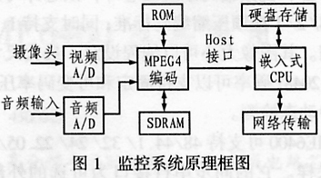
DA [14: 0]: SDRAM address bus, where DA [14:13] is connected to SDRAM ’s BANK [1: 0].
DNWE: SDRAM write enable signal terminal, low effective.
DNCS: SDRAM chip select signal, low effective.
DQM: The input / output mask of SDRAM data is enabled.
NRAS: SDRAM line address strobe end, low effective.
NCAS: SDRAM column address strobe end, low effective.
CKE: Clock enable signal terminal, high effective.
CKO: external SDRAM clock output. When reading and writing data from SDRAM, you should sample from its rising edge.
3.2 Video signal pin
IME6400 chip can encode the digital video signal of CCIR-601 interface. For the analog video signal from the camera or playback device, you need to conduct A / D sampling first to turn it into the required signal format. The functions of the video signal interface pins are described as follows:
VD [15: 0]: Digital YUV signal input terminal.
VSYNC: vertical synchronization signal, its active polarity can be programmed, the default is high and effective.
HSYNC: horizontal synchronization signal, highly effective.
DVALID: The effective indication terminal of the video signal. When it is low, it means that the video data is invalid; and when it is high, it means that the input video data is valid.
PCLK: Point clock input, the input video data is sampled on the rising edge of the clock. This clock should be provided by an external video A / D chip. Because IME6400 only supports 16bits video interface, it should provide a clock frequency of 13.5MHz.
FIELD: Parity indication end.
3.3 Static memory pins
Because IME6400 is based on a CPU core, so power-on initialization must start from ROM. There are two ways to start IME6400, one is through the internal ROM, and the other is through the static memory interface external ROM to boot. It is recommended to use an external ROM to guide the initialization of the IME6400. The pin functions of this interface are as follows:
ADR [16: 0]: Static memory address bus.
DATA [7: 0]: Static memory data bus. 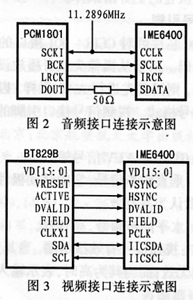
NRST: Reset signal of the main chip, active low.
MCKL: the main chip clock input, different frequencies correspond to different resolutions, when it is connected to high resolution, it should be connected to a 27MHz clock, at this time the image size can be 640 × 480, 720 × 480, 768 × 576, etc. 25 to 30 frames per second.
RAD [1: 0]: ROM low address signal.
RNOE: ROM data output enable signal terminal, low effective.
EXTBOOT: When the termination is low, the chip boots from the internal ROM; when it is high, the chip boots from the external ROM.
SNOE: SRAM data output enable signal terminal, low effective.
SNWE: SRAN data write enable signal terminal, low effective.
GPIO [7: 0]: programmable pins.
3.4 I2C interface pin
IME6400 can be used as the main device of I2C to configure the internal registers of the video A / D chip to manage the video A / D chip. The functions of the I2C interface pins are as follows:
IICSDA: I2C serial data terminal.
IICSCL: I2C serial clock output.
3.5 External HOST interface pin
The functions of this interface pin are as follows:
MODE [1: 0]: External HOST interface mode selection terminal? The specific selection methods are listed in Table 1. There are four modes to choose from. The system designed in this paper uses synchronous BURST mode 1.
Table 1 External HOST interface mode selection table
| Mode | MODE [1: 0] | CPU |
| Synchronous BURST mode 0 | 00 | PLX9050 / 9080 |
| Synchronous BURST mode 1 | 01 | MPC850 / 860 |
| Synchronous BURST mode 2 | 10 | CYPRESS EZ-USB |
| Asynchronous SINGLE mode | 11 | INTEL MCU |
BW: The bus width setting end of the external HOST interface. When connected low, the HOST interface adapts to 16 bits; when connected high, the HOST interface adapts to 8 bits width.
HD [15: 0]: External HOST interface data bus.
HA [4: 0]: External HOST interface address bus.
NCS: The chip select signal end of IME6400, low effective.
ADS: External HOST address strobe signal, low effective.
NRD: External HOST data read strobe signal, low effective.
NWR: External HOST data write strobe signal terminal, low effective.
FRD: The external HOST data reads the strobe signal terminal quickly, low effective.
USEOCK: Used to indicate the clock source used by the external HOST interface. When this pin is connected low, it indicates that the internal clock is used, and when connected high, it indicates that the external clock is used.
HCLK: External HOST interface clock output.
NFULL: Bit stream FIFO status signal terminal. When FIFO is Half-Full or Full, this pin outputs high level. 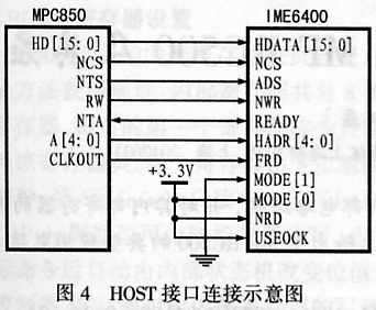
READY: When the interface mode is synchronous mode, this pin can be used to indicate the data preparation status.
3.6 Audio codec pins
The functions of this interface pin are as follows:
CCLK: Audio codec clock signal input terminal. IME6400 supports audio sampling rate of 32, 44.1 and 48kHz, in order to support different sampling rates, the input clock should also be different. When the CCLK input 12.288MHz clock, the system will support 32kHz or 8kHz sampling frequency; and when the CCK input 11.2896MHz, it supports 44.1kHz sampling frequency.
SATA: Input terminal of serial audio data line.
SCLK: serial audio clock signal output.
IRK: Left-right clock signal output terminal.
3.7 Other pin function description
CPUEST: Internal CPU test terminal, highly effective.
PLEST: Internal PLL test terminal, highly effective.
Funtest: chip function test terminal, highly effective.
DIV34: SDRAM's clock mode selection terminal. When it is low, it means that the clock frequency of SDRAM is 3 times that of the chip's main clock MCKL; when it is high, it means that the clock frequency of SDRAM is 4 times that of MCK.
4 Design of embedded monitoring system
Through the research on IME6400, the author designed an embedded monitoring system. Figure 1 is the design block diagram of the monitoring system. In the figure, after the audio and video signals are sampled by A / D, the data will be input to ISE6400 for MPEG4 compression encoding. The encoded compressed video stream is read by the embedded CPU through the HOST interface, and then can be stored on the hard disk or through The network is stored in other carriers.
4.1 Design of audio interface
In this design, the audio A / D sampling uses PEX1801 from TEXAS, which is a 5V powered dual-channel ADC. The input clock is 11.2896MHz, which can adapt to the sampling of 44.1Kbits. Figure 2 shows the connection between PCM1801 and IME6400.
4.2 Design of video interface and I2C interface
Video A / D selects BT828B from ROCKWELL. It can output digital video with CCIR-601 interface. BT829B has two sets of clock input. If you only use it to decode the video signal of the PA system, you should input the clock to XT0I and connect XT1I low. BT829B can be used as an I2C slave device to connect to the I2C interface of IME6400, so that IME6400 can complete the management of BT829. Its video interface connection mode is shown in Figure 3.
4.3 Design of HOST interface
The external HOST interface of IME6400 is mainly used to transmit the encoded data stream. The four external HOST interface modes can be determined by the MODE pin. The mode selected in this design is synchronous Burst mode 1, which corresponds to Mode? 1: 0? Pin = 2 'b 01. That corresponds to the situation of MPC850 / 860.
The embedded CPU can choose the MPC850 of the company MOTORALA. The HOST interface clock can be provided by MCK or FRD, and its value can be determined by the value of USEOCK. In this design, because USEOCK is 1, therefore, FRD is used as the internal clock source. This 27MHz clock source can be provided by the main control board. The connection mode of the HOST interface is shown in Figure 4. 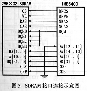
The MPC850 reads the compressed data from the HOST interface using the Burst method, and the NFULL signal of the IME6400 is directly input to the IRQ of the MPC850. Burst is programmable and is only used when reading compressed data. The maximum length of Burst is 256 bytes, that is, 256 bytes can be read in one operation. This shows that the design can greatly improve the reading speed.
4.4 Design of SDRAM interface
In order to compress video and audio data and store encoded streams, external SDRAM is generally required. Its size depends on the size and mode of the image to be compressed. The size of SDRAM selected in this design is 2MB × 32. IME6400 can access up to 2Gbits of external SDRAM. At present, the address size selected for this design is 11 rows and 8 columns.
SDRAM's clock is three times or four times the MCCK clock, which can be determined by the value of DIV34. In this design, the MCLK clock is 27MHz. When the three times MCK clock is selected, the clock of SDRAM is 27 × 3 = 81MHz. SDRAM selects K4643232E. The connection method is shown in Figure 5.
4.5 Design of ROM interface
If you use the internal boot ROM, the IME6400 does not require external ROM, but in external boot mode, you need a ROM interface. The external ROM can be up to 4MB. In this design, EXTBOOT selects the jumper method to control whether to use external or internal ROM to guide. The external ROM in this design uses 28C256, which is a 256KB (32KB × 8) and 5V-powered storage device. The 27MHz clock of MCKL is provided by the main control board.
IME6400 has two methods for downloading FIRMWARE, which can be selected by the jumper switch on pin P236 (EXBTOUT). When the jumper switch is high, the external 28C256 is selected to start, and when it is low, it starts from MPC850.
5. Advantages of the monitoring system
The MPEG4 compression and embedded system designed with IME6400 hardware can greatly improve the performance of the monitoring system, mainly in:
(1) The video and preview are also clear, the image format can achieve D1, and the full dynamic bit rate can be controlled at 200MB / hour.
(2) The compression speed is faster, and there is no lag delay during real-time streaming. The minimum delay can be less than 1 second.
(3) The compressed data can be read in Burst mode, which improves the reading speed, and also creates conditions for the adoption of embedded CPU.
6 Conclusion
This paper provides a real-time audio and video compression technology solution for MPEG4 through the analysis of the MPEG6400 chip. And designed an embedded MPEG4 video surveillance system for commercial use.

Follow WeChat

Download Audiophile APP

Follow the audiophile class
related suggestion
This article introduces the MPEG audio codec and its applications, and presents the most successful creator of modern audio coding ...
In order to overcome the shortcomings of MP3 storage capacity, expensive price, complicated operation, unity of playing songs and so on in the current market, a basic ...

MPEG (Motion Picture Expert Group) audio compression standard provides a high fidelity, high ...

"The father of MPEG" Leonardo Chiariglione initiated, aims to create a set of open source software ...
Compression format refers to the video using digital compression technology, common are DV, MPEG-2, M-JPEG, etc.
AVS uses many advanced technologies to ensure its performance, which is a new standard with more advantages. Part 2 of the AVS standard completed at the end of 2003 ...

This article introduces the international video coding standard mpeg in detail, and introduces the key technology of AVS video.
This article from a technical perspective on MPEG-2 video standard, MPEG-4 AVC / H.264 and AVS video (GB / T 20 ...
1 The development and characteristics of MPEG 1.1 MPEG-1 Before the advent of MPEG, the image compression has been ...
ST launches full-definition H.264 / MPEG system-level chip FLI7510 STMicroelectronics for global flat-panel digital TV (DTV ...
MPEG Development History MPEG was originally MovingPicturesExpertsGroup, dynamic image expert group ...
MPEG1, MPEG2 image compression MPEG-1 MPEG-1 system ...
Software implementation of MPEG-4 in video surveillance application This article mainly discusses MPEG-4 in video surveillance based on the characteristics of video surveillance ...

Single chip DSP implementation of MPEG sound coding 1 MPEG sound coding principle ...
Abstract: A brief introduction to the characteristics of field programmable gate array (FPGA), combined with ...

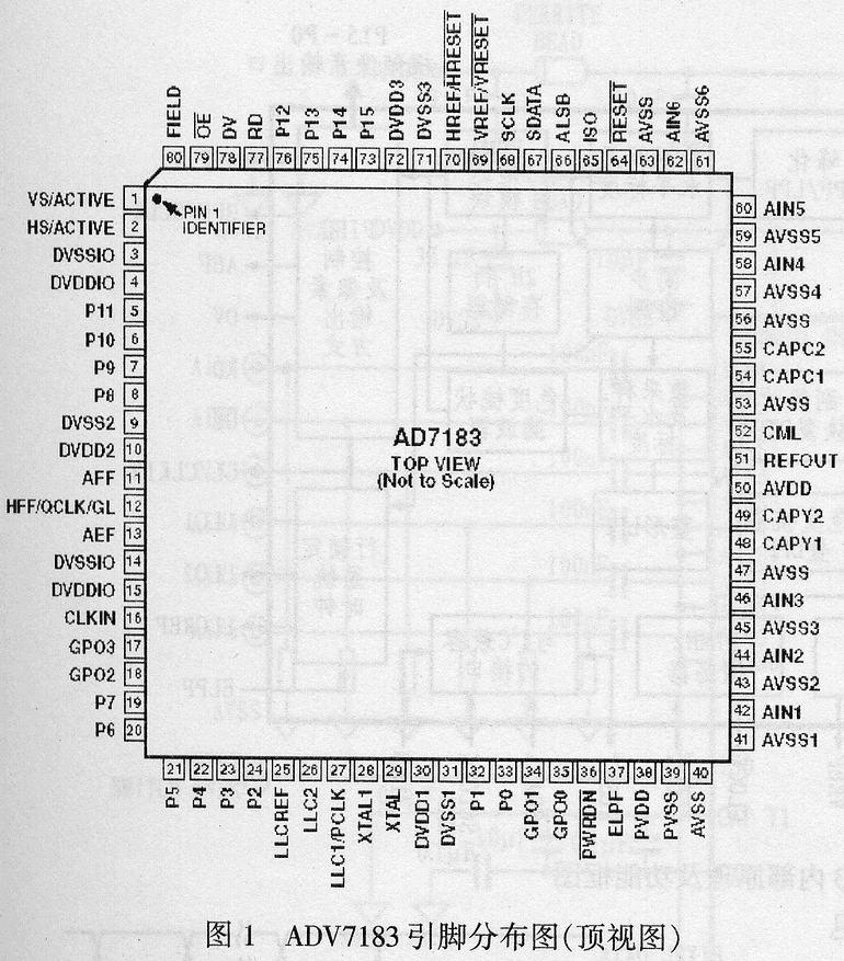
Abstract: ADV7183 is an enhanced video decoder with 10-bit ADC integrated by American Analog Devices (ADI). Inside it ...
Three-terminal ...
![[Photo] Three-terminal voltage regulator XWY2005 and its application](http://i.bosscdn.com/blog/20/06/41/7212011242.jpg)
...
High Accuracy CMOS Operational A ...
![[Photo] High-precision CMOS operational amplifier LMC6062 / ...](http://i.bosscdn.com/blog/20/06/41/6175842568.gif)
Abstract: NCP1
![[Photo] Single-ended PWM controller NCP1205 and its application](http://i.bosscdn.com/blog/20/06/41/6173136914.gif)
NE605 is Philips ...
![[Photo] High performance small power FM receiver chip NE605 and its application ...](http://i.bosscdn.com/blog/20/06/41/5192033610.gif)
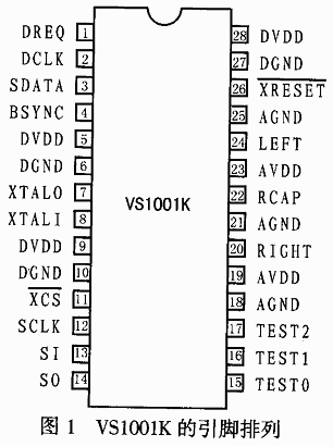
Abstract: VS1001K is a new MP3 decoder chip produced by VLSI Solution of Finland. The chip contains high quality ...
Abstract: TDA9332H is a display processor suitable for high-end color TV produced by Philips, which can be used for single scan (50 or 60Hz) and dual ...
Introduction
Abstract: The parallel interface high-performance ferroelectric memory FM1808 produced by RAMTRON is an ideal substitute for NV-SRAM ...
Abstract: Introduces the features of the zero-power ultra-fast and complex programming logic device ispMACH4000Z introduced by Lattice Semiconductor, ...
This article introduces the main features, pin functions, software design, hardware connection and specific application circuit of PTR2030. PTR2030 is super ...
XTR110 is a precision voltage / current converter launched by Burr-Brown Company of the United States. It is designed for analog signal transmission ...
Abstract: This article introduces the MAX712 / MAX713 programmable battery charge management chip produced by MAXIM, using MAX ...
Abstract: This article introduces the principle, characteristics and pin functions of the embedded microprocessor MCF5249 of MOTOROLA company, and explains ...
Abstract: Based on the analysis of the ARM architecture, the structural characteristics and advantages of the 32-bit ARM core processor W90N740 are introduced ...
Abstract: This article introduces in detail the basic principles, features and original use of the digital tube and keyboard smart chip zlg7289A ...
Abstract: This article introduces the structure, function and interface characteristics of OMAP5910, and ...

Abstract: The basic principles of digital watermarking technology are introduced. Taking MPEG-4 as an example, an improved spread spectrum-based video is proposed and implemented ...
Abstract: CS6208 is a chip specially developed by Myson Century for network control and transmission. It is based on 80 ...
