How to perform voltage transient test on in-vehicle electronic products
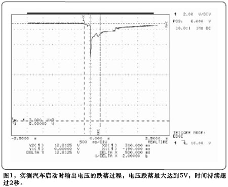
With the rapid development of the automobile industry, in order to meet people's requirements for automobile safety, environmental protection, energy saving and comfort, the application of in-vehicle electronic products is becoming more and more popular. Due to the complex output of the automotive power supply system, high-current motors, solenoid valves and other components cause the power supply voltage output to often fluctuate, and large voltage pulses or drops frequently occur (Figure 1), which will challenge the stable operation of electronic products in the car , Especially safety-related electronic products, such as airbag control circuits, ABS control circuits, etc. Unusual voltage fluctuations will cause the CPU or other chips of these devices to enter a restart, lockup, or unknown state, which directly affects the safety of people in the car.

Figure 1 The measured output voltage drop process when the car is started. The voltage drop reaches a maximum of 5V for a period of more than 2 seconds
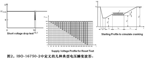
How to simulate the voltage transient phenomenon in the actual power supply system in the laboratory, so as to discover the hidden dangers of vehicle electronic products as early as possible has become a problem that is concerned by the majority of automotive electronics product development and design verification personnel. To facilitate testing, the International Organization for Standardization provides a series of voltage transient waveform test templates (Figure 2) to simulate voltage waveforms in various situations. Such as ISO-7637, ISO-16750 and other documents, to predict the voltage transient waveform of the car in various operating environments, engineers can test the test piece according to the voltage waveform defined by the template in the laboratory to judge the product Whether it meets the requirements.

Figure 2 Several typical voltage transient waveforms defined in ISO-16750-2
Completing this type of test is usually more difficult, because the transient voltage drop or overshoot phenomenon is often fast, the waveform is special, and it has a certain power output. Although the function generator has sufficient bandwidth and easily generates various waveforms, the output power is very small (usually at the milliwatt level) and cannot be used to drive the DUT. Although the ordinary power supply has high power, the output voltage changes slowly. By programming the power supply output, it can only generate a simple waveform that changes in seconds, and cannot reach the voltage transient speed defined in the test template.
Selecting a power supply with analog programming function can increase the frequency range of the power supply output waveform to a certain extent. The power supply with analog programming function in the system is equivalent to a power amplifier, which amplifies and outputs the waveform signal input from the analog programming terminal in proportion. The system structure is shown in Figure 3:

Figure 3 uses the analog programming method to output the voltage transient waveform
This method can generate some complex waveforms, and the function generator drives the power supply to generate voltage transient waveforms with power. However, due to the limitation of the power supply speed, the frequency of the output waveform is limited to a range of tens of hertz. In addition, the analog programming method will cause the output voltage accuracy to decrease.
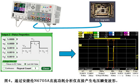
High-speed power supply is the most ideal method to complete voltage transient test. For example, the Agilent N6705A DC power analyzer, with rich front panel functions, can define various voltage transient waveforms without programming (Figure 4). And directly observe the actual curve of power supply output voltage and current on the front panel screen.

Figure 4 The voltage transient waveform is directly generated by the Agilent N6705A DC power analyzer
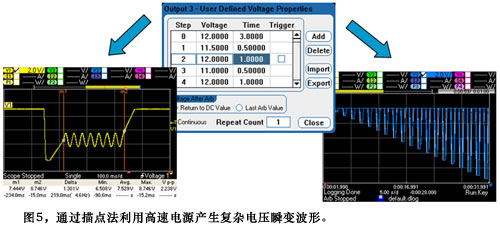
Complex voltage transient waveforms can be achieved by plotting. In Figure 5, the output on the left corresponds to the typical voltage drop waveform when starting the engine as defined in ISO-16750-2. In the waveform on the right, each voltage drop increases by 5% until the electronic device under test restarts. This test is used to determine the restart voltage of the on-board electronic device.

Figure 5 uses the high-speed power supply to generate complex voltage transient waveforms through the tracing method
The test template provided by ISO can predict the voltage transient waveform generated in the power supply system in most cases, but the template test still cannot fully cover the voltage change in the real power supply environment. Because the actual application environment is different, the vehicle electronic products must be tested in the real environment before they can be considered to meet the design requirements. Real environment testing requires placing the DUT in the vehicle environment, and even connecting it to the engine, actual vehicle load, and other equipment. The test conditions are very complex, and the frequency of the occasional voltage change waveform is very low, difficult to control, and requires repeated testing Get the required test conditions. In order to simplify the test method, the engineer hopes that these occasional voltage waveforms can be reproduced by the instrument in the laboratory, and it is more convenient to complete the actual environmental test.
Nickel Iron Battery,Nickel Iron Alkaline Battery,Solar Battery,Nickel Iron Battery For Solar
Henan Xintaihang Power Source Co.,Ltd , https://www.taihangbattery.com