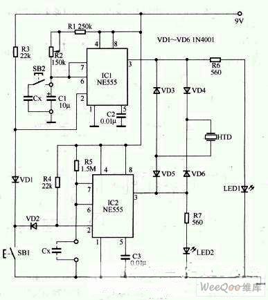
Intelligent capacitance tester circuit
The figure shows the circuit diagram of the intelligent capacitance tester. The circuit is mainly composed of three parts: a reference circuit, a test comparison circuit and an indication circuit. In the capacitance tester circuit, TCI constitutes the test reference circuit, which is a monostable circuit composed of NE555 and R1, R2 and C1. SB1 is its trigger button switch, and the monostable circuit is started after pressing SB1. The transient steady-state time of the monostable circuit is determined by Tdl 1.l(R1+R2)C1. Changing the value of any one of the components, Td1 changes, and the output state of the circuit also changes. IC2 constitutes the measured capacitance test comparison circuit, which is another monostable circuit composed of NE555 and measured capacitance Cx.
If the measured capacitance Cx and the reference capacitance CI have the same capacity, and the Td of the two monostable circuits are equal, the ICI and IC2 simultaneously output a high level when the SBI is pressed, and the two circuits simultaneously return to low power after the delay is over. level. At this time, LEDI and LED2 emit light at the same time, but both ends of the HTD do not sound due to the simultaneous equipotentiality.
If the measured capacitance Cx is greater than CI, the measured capacitance Td2 is greater than the reference capacitance Td1. At this time, when SBI is pressed, the two circuits are simultaneously started and delayed, and the ICI is first restored to a low level by the high level, and IC2 is subsequently restored to a low level. After ICI first resumes high level, since IC2 is still high, the moment when ICI changes from high level to low level occurs. The high level of IC2 output forms loop through VD6→HTD→VD3, making HTD A "beep" sound is emitted, and the LEDI is first turned off.
If the capacity of the measured capacitor ex is smaller than the reference capacitance CI, the output of IC2 is first restored to a lower level than the IC. The output circuit will form a loop from VD4 → HTD → VD5, and a "beep" sound will be emitted at the moment when IC2 returns to a low level, and LED2 is first turned off.
machining
Henan Yongrong Power Technology Co., Ltd , https://www.hnyongrongglobal.com