[Source: Engineering LED's "LED good product" 9 monthly magazine text / Xiao Jinhua] LED lighting driving power source on the market are usually divided into two categories - linear power supply and switch mode power supply. The linear power supply structure is simpler but less efficient. Switch mode power supply efficiency is high, but the design is complex, electromagnetic interference is large, electrolytic capacitors must be used, this will be the bottleneck affecting the life of the switching power supply.
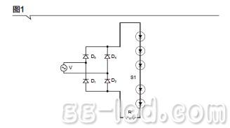
Figure 1 shows the most basic linear electroless capacitor LED driver. In this circuit, the LEDs can be driven directly by the AC source V without the use of complex converters. In the operation of the illustrated circuit, the AC voltage is converted to a rippled DC voltage via a D1~D4 bridge rectifier, and whenever the voltage value is higher than the forward threshold voltage of the LED string S1, the LED string S1 is turned on and illuminates. Resistor R limits the current flowing through LED string S1.
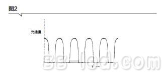
Figure 2 shows the light output (light flux versus time) of the LED circuit of Figure 1. It can be seen from the figure that the turn-off time of the circuit is about 40%, because the LED current is discontinuous at the zero crossing of the AC voltage waveform. The rectified AC line voltage is cycled from zero to peak voltage and back to zero, so the LED string is turned off as long as the line voltage level drops below the forward threshold voltage of the LED string.
In order to preserve the simple structure and connection of linear drive power, while reducing the light-off time associated with LED circuits, improving efficiency and power supply life, many IC manufacturers propose to change the number of LED lamps that are connected when the input voltage changes. Capacitive linear constant current source drive scheme increases the LED illumination time during the entire AC cycle, thereby increasing LED utilization and total output lumens.
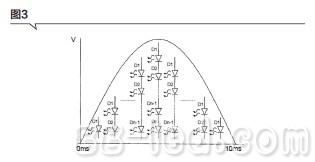
In these schemes, the high voltage LED string is divided into n LED arrays D1 to Dn, where n>1. Figure 3 is a graphical representation of a forward voltage string generated over a half cycle. As can be seen from the figure, the forward voltage string initially includes only the LED array D1. As the power supply voltage rises to the sum of the thresholds of D1 and D2, the LED array D2 begins to conduct, and D1 and D2 simultaneously emit light. As the supply voltage reaches its peak, the forward voltage string includes the LED arrays D1-Dn, and the entire LED string illuminates. Then, as the voltage of the power supply drops, the forward voltage string is again lowered to only the LED array D1.

Figure 1 shows the most basic linear electroless capacitor LED driver. In this circuit, the LEDs can be driven directly by the AC source V without the use of complex converters. In the operation of the illustrated circuit, the AC voltage is converted to a rippled DC voltage via a D1~D4 bridge rectifier, and whenever the voltage value is higher than the forward threshold voltage of the LED string S1, the LED string S1 is turned on and illuminates. Resistor R limits the current flowing through LED string S1.

Figure 2 shows the light output (light flux versus time) of the LED circuit of Figure 1. It can be seen from the figure that the turn-off time of the circuit is about 40%, because the LED current is discontinuous at the zero crossing of the AC voltage waveform. The rectified AC line voltage is cycled from zero to peak voltage and back to zero, so the LED string is turned off as long as the line voltage level drops below the forward threshold voltage of the LED string.

In order to preserve the simple structure and connection of linear drive power, while reducing the light-off time associated with LED circuits, improving efficiency and power supply life, many IC manufacturers propose to change the number of LED lamps that are connected when the input voltage changes. Capacitive linear constant current source drive scheme increases the LED illumination time during the entire AC cycle, thereby increasing LED utilization and total output lumens.
In these schemes, the high voltage LED string is divided into n LED arrays D1 to Dn, where n>1. Figure 3 is a graphical representation of a forward voltage string generated over a half cycle. As can be seen from the figure, the forward voltage string initially includes only the LED array D1. As the power supply voltage rises to the sum of the thresholds of D1 and D2, the LED array D2 begins to conduct, and D1 and D2 simultaneously emit light. As the supply voltage reaches its peak, the forward voltage string includes the LED arrays D1-Dn, and the entire LED string illuminates. Then, as the voltage of the power supply drops, the forward voltage string is again lowered to only the LED array D1.

>>>Unfinished , please refer to the September issue of Gaogong LED 's " LED Good Products" magazine.

We've been around for over 16+ years. We make sure our sound is The Best Sound.
Manufacturing high-quality products for customers according to international standards, such as CE ROHS FCC REACH UL SGS BQB etc.
wholesale earbuds, earbuds in bulk, earbuds custom, true wireless earbuds
TOPNOTCH INTERNATIONAL GROUP LIMITED , https://www.micbluetooth.com