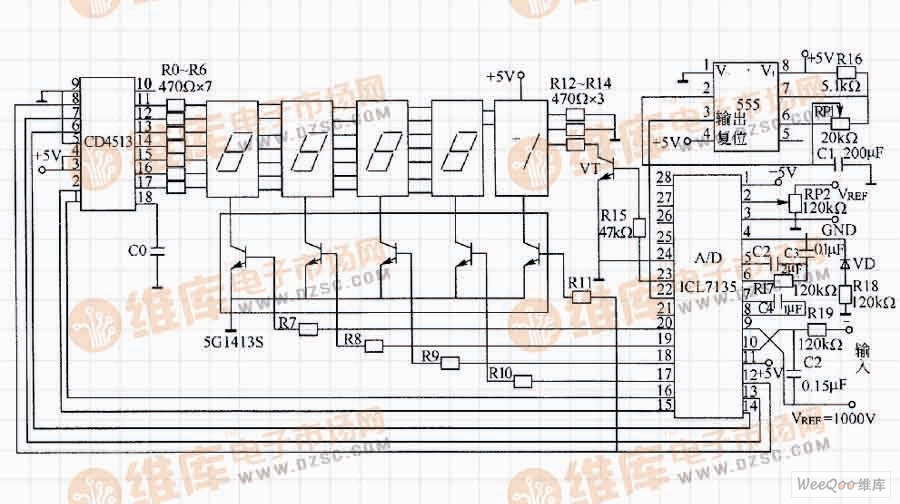
Digital voltmeter circuit composed of 555 base time circuit and digital tube
As shown in the figure, it is a digital voltmeter circuit composed of a BCD-7 segment latch/decode/driver CD4513, a 555 time base circuit, and a digital tube. The circuit is mainly applied to a digital voltmeter circuit.
The astable multivibrator consists of 555 and R16, RP1, C1, and generates a clock for A/D conversion. The A/D converter can convert the input analog signal into a digital signal output, and drive the common cathode digital tube through the Darlington tube 5G1413S. The CD4513 provides an output display driver that adjusts RP1 so that the 555's oscillation frequency is around 120kHz.
Led Sign,Led Display Sign Board,Customized Led Display,Customized Led Display
ShenZhen Megagem Tech Co.,Ltd , https://www.megleddisplay.com